Tuesday, March 3, 2020

T19: Stock assembly revision 3, inverter cover minor printability fix, randoms.


A few product-improvement variety tweaks to the same old stock design that had been deferred since the early days.

One, I bothered to make a curved buttplate for it. Fits all T19 stocks.


Two, switch fences have been added.

I have never accidentally turned my blaster off in combat, but that would not be good.

This is a traditional strategy for guarding switches to prevent them from getting bumped and moved accidentally.


Three, the front edge of the stock body has been chamfered.

And four, the stock body and base have 10-24 counterbored SHCS holes to secure the 1" PVC buffer tube. Insert tube, align stock and base, mark/drill, tap, install fastener. No more friction only nor permanently Devconned stock assemblies where you replace 3 parts if one gets broken or you want to upgrade or mod one.

These inverter covers always had some trouble printing cleanly:


Take a close look at that bottom edge - it doesn't immediately look like a problem, but the fluting comes across the edge at a low angle and the resulting geometry FDMs only slightly better than flaming garbage. These always got some attention from a razor blade afterward and still tended to look like shit and have a horrid jagged edge. Drove me up the walls for over a year, but it's sometimes difficult to bother with minor things like that that have zero bearing on function whatsoever.

Now, there could be a lot done to smooth and de-brutalize the architecture and these covers are a great example, but that's not the idea here. I will do something to that effect as part of a larger remodel that is not strictly part of Model T19 at all, but T19 is what it is, and is going to continue being brutalistic.

Don't like it? Rant time. Design your own mod bits for it or reshell it yourself. I'm not your CAD slave.

The more flak and the more barf emojis on poisonous Discard channels I get about my style from certain toxic individuals who do not design blasters of this sort themselves, attempting to demand that I change my ways for them when they have no interest in running my equipment anyway; the more I shall stick to the brutalism - especially as locals who actually handle and shoot and look at these in person and are my actual customers as a designer besides my own use do not agree given how much demand I am getting. Let's make this clear, I have no tolerance for politics, and no tolerance for assholes, and trying to "community politic" me or being an asshole to me is not going to get anything whatsoever out of me especially when it's about something totally subjective.

The level of entitlement some people have in general toward open hardware/open source designers across the community who release ridiculous amounts of work for free is astounding. I know many of the same crowd dissing the 19 also attacked FDL Jesse for the FDL-2, do not try to deny that shit, and I know he was NOT happy about that either, and you should be ashamed to be a thorn in the side of multiple designers. Rant over.

Printability fix.


Straightforward matter of stopping those two fluting "toolpaths" a bit short to not bust through the edge. Problem solved.

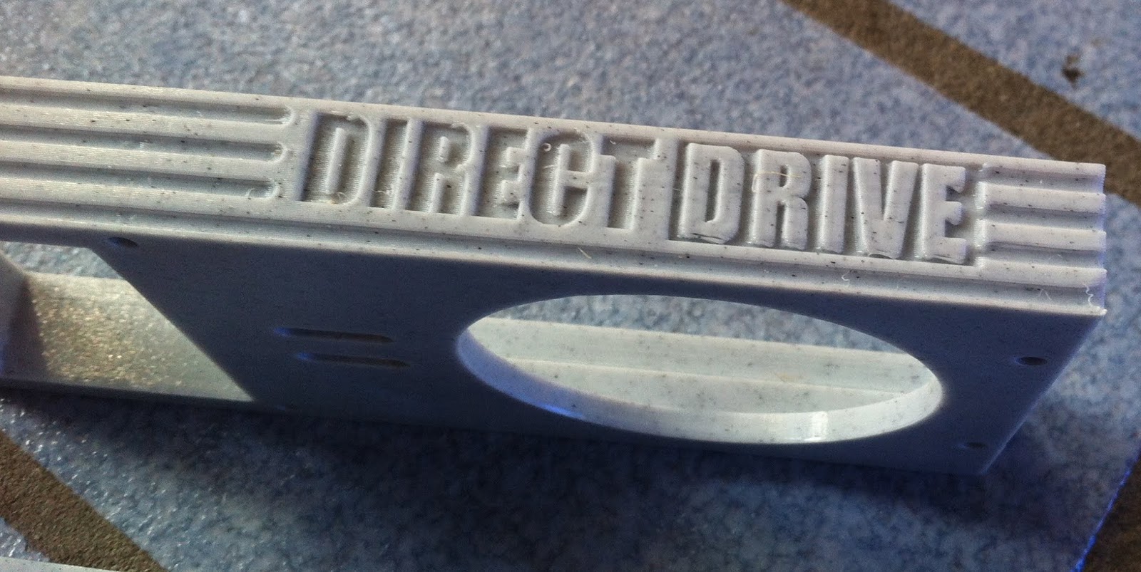
I also started doing printability experiments with various orientations and types of 3D text/graphics on my setup/materials. I have always thought a lot of designers went over the top with text and logos and greeblies, and so I have long resisted spewing badges all over mine. One thing I will ALWAYS do is to release a complete set of badge/text-free part files for every blaster. But I at least want to know the limits and the results of printed-in badges, for more subtle and boring things like model/serial/build date tags if nothing else. So time to do some test parts.


I had had this DIRECTDRIVE badge thingy in mind for a while and it tested both positive and negative text oriented on the side of a part ortho to the bed, and it has some big horizontal overhangs and some fine little features... Good stress test.

Then there's this one:


Tacky and OTT perhaps, but at least one of my personal Things needs a proper snipe at DC motors plastered on the side. I have fond memories of a certain rental Yale reach truck at work that was, like my blasters, fully brushless, and had (you guessed it) these big, tacky, over the top AC POWER badges. These covers make a good test case for bridged negative features facing the bed, and are the most likely place to put "nameplate" type stuff. A lot of people do it on FDL-3 sideplates, but the outside surface on those is a top layer.

Liking the results of both. Pretty much as it came off the machine, haven't even picked out any strings or blobs yet...


I'm surprised how well printing this doesn't fail. Sometimes, FDM is PFM.


And these come out nice and sharp too. Be mindful of elephant footing if you're going to do these sorts of things. Would really look nice as a multimaterial, obviously, if you wanted to do something less subtle like put your username there.


Silly stuff mostly. But the resolution is better than I expected and could easily resolve smaller text.

Wednesday, February 26, 2020

S-Core Firmware 0.95 - Home bolt with flywheels turning at low speed; more robust and snappier speed-based feed control.

Link

Changes:


  • Home bolt with flywheels turning (at default low speed)


The previous selftest routine reset the bolt at startup with the flywheels stopped. Occasionally, such as in the case where a stoppage or debris is present or the bolt is not homed but a loaded mag is present, this would mash something into stationary flywheels.

Now we wait until after the flywheel drive rotation check and run the wheels at low speed while homing to spit out anything that is accidentally fed. If something is fired inadvertently during this procedure, it is barfed out at about 36fps, so this is safe - assuming you have an ESC firmware with default minimum speed, which you should.

  • Improve speed-based feed control

A series of consecutive in-range tach readings (the number of which is still a build-time setting) are now required to initiate firing. This removes most possibility of enough randomly in-range pulses being received during the timeout window to fire when a drive is not actually at speed. This might happen during a stall condition while tach pulses may be clipped by start timeouts and/or there may be motor vibration which is capable of creating in-range tach pulses.

Offset margins and such have been revised slightly and control is a good bit snappier. Some perturbing of these settings may be called for to fine-tune velocity consistency, but it shoots pretty damn nicely with my Emax equipped primary.

03-04-20 Update: I have hotfixed some configuration parameters in this release. Posted as a Google Drive version, so should be transparent.


  • Set maximum flywheel RPM back to 25,510 since 26,000 is a deleterious overspeed for the Hy-Con and resulted in a decrease in mean velocity and an increase in velocity spread.
  • Make STC settings a bit more conservative since while it got consistent velocity at 50/25, how I had it set may have been edging toward not getting max velocity in lieu of snappiness in a few cases. This does expose the SimonK mid-speed transient response bug more as a slightly more delayed followup shot at certain speeds, but that's OK.

SimonK FlyShot (digital speed command, closed-loop) - Default to safe minimum speed on boot, etc.

Code (plus a precompiled bs_nfet.hex for ACE discrete drive and Spider boards, etc.)

Now defaults to ~35,000erpm (~5000rpm with 14 pole motors, or about 36 fps root speed on a standard Hy-Con) at boot time.

Also, the safety governor (safety here being from the ESC's perspective, meaning avoiding exceeding the frequency limit of the inverter control loop) has been set back to the stock TIMING_MAX = 0x0080 (312,500erpm) in this so this is now universal to high speed applications out of the box whereas me leaving it at 0x00e0 in the last one may have "gotcha'd" someone.

/u/matthewbregg had a good suggestion in this thread about defaulting to a low speed. I had been considering this type of feature, but this thread got me thinking about safety and failsafe control a bit more in general. Thus this, and the new velocity watchdog code on the S-Core's end.

It really makes sense just in general that a closed-loop drive doesn't try to spin to the moon if you haven't informed it of what speed it should go... Makes sense, right?

Some setups (very large wheels and high-velocity multistages in particular) could even conceivably be mechanically intolerant of overspeed. With ordinary BLDC configurations, that wouldn't happen, because the battery and motor kv would have been selected to avoid that, but with closed-loop configurations that are trying to have stiff speed regulation with a lot of available torque at some operating speed, it may very well be that there is enough bus voltage that reaching hazardous speeds and blowing shit up is possible if uncontrolled. My previous idea was that one would just set TIMING_MAX to an appropriate safety governor setting which removes the need for a default low speed in that regard, but in general, flashing ESCs to configure them is a pain in the ass and it is better to make a drive firmware be universal and live-configurable over the wire.

Bregg also implemented a version requiring identical FlyShot commands to be sent twice to apply a speed update, and this is a most excellent addition for applications that do not have speed feedback and cannot selftest their flywheel speeds, like most Ultracage setups and FDLs and whatnot. These variants are also compatible with my gear by nature, but the above code doesn't have that feature because I want a higher speed update rate and smoother speed adjustment when live-adjusting speed and it is not necessary to be that overzealous with speed feedback present. In any case, just like Dshot commands, one-time FlyShot commands should always be sent about 10 times anyway as a matter of course.

Wednesday, February 19, 2020

Hy-Con Delta Cage released - Long forend, support for Emax RS2205S.

With the Turnigy V-Spec getting scarce, it is time to option more motors. I also had some requests for longer barrels and more rail estate on the T19 platform.

Bird 1 and bird 2, let me introduce you both to this stone. Hy-Con model Delta:


All STEP and mesh files


This is equipped with a new motor option, Emax RS2205S. This, like most drone-market motors, is a threaded shaft motor.


It is widely available, torquey, not too expensive, and very axially short, which removes most of the bulges/stuff sticking out annoyingly that tend to be problems for thin-packaged horizontal cage rigs when transitioning over to threaded shaft motors from bolt-pattern motors. There are just some ~2mm tall hole plug heads on the bottom of the cover. These plugs result from keeping the old school cover dimensions, no real reason or rhyme to why I did it that way.


I do have plans to multiplex things a bit more between cage variants and motor options as I test and add more, but the Gamma Major short barrel cage really just needs a clean sheet redraw and some more polishing anyway. So for now, it's Gamma/Turnigy or Delta/Emax.


The wheel, being that this is a threaded shaft motor, has some new features.


Locating keys specific to the Emax are provided to fit into the rotor notches and allow the shaft to be held with the wheel for initial torquing of the nut.

This is a rotor OD piloted wheel and the shaft hole is a large clearance on the shaft to avoid overconstraint as usual.

A slight counterbore is provided to match a raised boss around the shaft on the rotor of the Emax motor and give full surface contact.

The ring of tiny holes is a toolpath control/selective infill feature to force the slicer to generate solid plastic in the web where the clamping load is applied.

A printable washer is used under the shaft nut to account for surplus unthreaded length. The web thickness is not increased unnecessarily (Ultracage) to this end as this has no structural purpose and adds a lot of inertia that might best be made optional. (Still, with how these run, I might slice wheels for them to add some more inertia anyway in the future.)

There are no left-hand threaded versions of this motor and they come with nylon insert locknuts, so don't go looking for a "CW and CCW pair" of them.

As per my usual design approach, this is a nonventilated wheel design. Excessive motor temperatures have not been a concern whatsoever.


I am not putting up anything except 9.5mm gap wheels with this and going forward. Closed-loop speed control completely removes the entire issue of "subcritical speed = bad" - subcritical with stiff speed regulation is actually a route to world class velocity consistency. The 9.5mm wheels turned down are easy on darts and very consistent.

Rails: Self explanatory.


Overall I am satisfied with the Emax RS2205S. It delivers a slight improvement in flywheel drive response versus the old Turnigies (which on the new control gear is automatically translated into a reduced feed delay without changing any settings! So much nicer than manual tuning) and is another, and more solid/trustworthy than the Turnigy, option but I don't quite like their "personality". They are modern, and aggressive, with N52 arc magnets, and tight airgaps. With so much field flux, the cogging torque is pretty gnarly, and they feel and sound more harsh. (They don't coast as well either - adjust your driveCoastTime down a bit if you have old world controls.) It's much like 3240s vs. XP180s in the old dark DC days. Sure, the latter has more torque and is objectively better, but the former feels... Happier. Same here, which is why for further motor options I am going to include some other motors with more Turnigy-like magnetics. The Racerstar BR2207S is one I already have on hand which is a sweet amazing sounding runner, and I will also be testing their BR2406S and perhaps BR2306S as all of these are cheap and plentiful.

Sunday, February 16, 2020

S-Core new firmware features: power-on selftest, flywheel overspeed detection.

Link up front

The source is the best documentation for the details, but selftest is very much no longer a placeholder. Overview of all checks in order:

Bolt drive system

  • Verify that the bolt can be homed as determined by the limit switch within one revolution. Issues with the limit switch fail, as do a drivetrain that has locked up/jammed with FOD or become disconnected from the motor, and inverter failure or an unplugged motor (obviously).

Trigger input

  • Verify that the state of the complementary trigger inputs is a valid high/low or low/high state corresponding to a switch up or down position, rather than a high/high or low/low state corresponding to a failed switch, a short, or a bad connection.

Flywheel drive system

  • Verify at least casually, without using interrupts, that tach lines sit at a stable logic state while motors are undriven. This avoids a race condition risk that is posed by enabling external interrupts if the tach line may have become connected or coupled to a high-frequency noise source or signal that was not anticipated.
  • Verify that each flywheel drive emits tach transitions within one timeout period when throttled. This catches drives that have become unplugged, don't have power or otherwise are totally inop or absent.
  • Verify that each flywheel drive can spin its motor past a minimum speed and keep it there for a minimum number of check cycles during the timeout. This finds seized motors, and typical single-phasings and partial inverter failures that may still move the motor but can't actually drive the motor to any speed.

Closed-loop speed control integrity

  • After setting and locking down the speed prior to entering normal operation (either by defaulting to the current tournament lock setting or by exiting the user speed configuration mode), spin up flywheels and verify that, within a timeout period:
    • No single tach periods indicative of critical overspeed events occur.
    • The noise-filtered speed of each drive falls within margins of the speed it ought to be set to for many consecutive check cycles.

Combined with an ESC firmware that defaults at its own boot to a very low speed setting, this one boot-time check renders some unforeseen signalling issue, drive reset or bug causing considerably hot velocity effectively impossible.

To report the results of these self-checks when they fail, the familiar construct of "fault codes" now shows up here. These consist of a "major" and "minor" component and are organized approximately by fault category or subsystem.

The stepper motor is conveniently useful as an audio/tactile feedback device. It is used to emit a (not too loud) alarm, then blip out the fault code responsible using "growls" (familiar to anyone who has turned on an old T19): first major, then 700ms of silence, then minor. Both values are always to be greater than 1, and I prefer that they be less than 9 for brevity.

So far there are only codes for selftest failures or drive overspeed events, codes do not persist past the current boot, and all faults are also terminal and disable operation, as all of the current ones in a strict sense render operation either impossible or potentially unsafe.

The center blaster below is running this code right now and it is effective and solid.


This image was at CFDW. The lower left-hander blaster with the rail on the cage is Junior7's unit which I updated the firmware on at the event (to 0.8) and swapped out the selector switch (more on this switch later). I haven't posted that build in detail - it's a 221 with S-Core 1.0, ACE LC1s, Turnigy Vspecs, a lefty stock base, lefty auxiliary controls, plus an underbarrel rail and one very long mag release that he wanted and filaments are Atomic marble, Atomic translucent aqua and Yoyi translucent orange.


Same blaster's print kit before assembly.

Friday, February 14, 2020

S-Core SBBM v1.5

The original S-Core did its duty as a dev mule, but it's time for a "production" board for both me and other people to use.


Changes:

  • Delete the solenoid driver - It is decided. Steppers are NOT going anywhere.
    • Solenoid-driven magfed applications are going to get their own, smaller, simpler board. If a coil driver is needed at the same time as the DRV8825, that can be something plugged into the GPIO connector.
  • Switch pusher motor DC link cap and logic power supply filter cap to through hole 10mmOD electrolytics - No more SMD lytic hassle. Also, cheaper, and many options of lower ESR which matters for the former.
  • Fix inductor footprint near AOZ1282 for easier soldering
  • Fix MCU ceramic resonator footprint for easier soldering
  • Put all components on front side - Does it matter? Not really... There's through-hole leads sticking out the back for all the headers and such so you can't whack it against a flat surface anyway without some standoff but it felt right to do this. When I do the mini version, this likely won't be the case.
  • Add mounting holes
  • Replace cheesy little Bourns TC33 trimpot for tournament lock with a Bourns 3362
  • Replace DC bus wire pads with wire holes plus 2 pin 0.1" connector footprint for options and better wire management in-blaster
  • Add TVS diode footprint (SMA package) for DC bus transient overvoltage protection (opt.)
  • Change BOLT connector to 2 pin
  • Change GPIO connector to 4 pin (adding pin formerly eaten by the solenoid driver)
  • Add ISP header pinout legends (Not shown in the above render)
  • Add motor drive pinout legends (Not shown yet as well)
  • Improve MCU decoupling
  • Via stitch front and back ground planes generously and improve ground connectivity/impedance to everything
  • Circle VREF test points in the silkscreen, if they needed to be any more obvious
30x75mm. 2 layer, 7/7mil, 1oz. Minimum drill 20mil (I use large vias by habit) Should be easy stuff to get made by any vendor.

Monday, February 10, 2020

S-Core firmware 0.8 and new feature overview.

This is the firmware these new blaster manager boards run.

All the important (um) core functionality is there and solid - the main bit left to work on, really, is just doing a proper power-on selftest now that we have the hardware capabilities to. Beyond that, it's mainly a matter of implementing alternative UI behaviors that I or anyone else wants.


So into all the new stuff.

- Implementation of FlyShot protocol; integration with adjustable-speed flywheel drives


The protocol described in this post is implemented.

Support on the motor controller's end is required. This may become a compile time option, but in general, avoiding ESC reflashing and setting speed over the wire from the blaster manager's end is easier and more flexible, even if you program your blaster manager to set a fixed speed only.

- Implementation of speed feedback-based feed control (=closed-loop single-trigger control. CLOSE ALL THE LOOPS!!)


"Blind" feed delays/delay scheduling approaches to account for motor acceleration with no awareness of actual wheel speeds are so last decade and really needed to go, just as much as open-loop voltage command flywheel drives needed to go. In particular:

  • Scheduled delays require tedious manual tuning to closely match the dynamics of a given flywheel/drive system and produce snappy shots, but consistent velocity, under a variety of conditions. Oftentimes they get just "Meh, good enough!"-ed to the generous side by a builder who can't be bothered squeaking every millisecond of latency and every fps out of the damn thing - including me.
  • Scheduled delays cannot, obviously, react whatsoever to unanticipated variances. This could be anything from a change in DC bus voltage and sag due to batteries not being ideal and varying in voltage and IR with SOC and temperature, to a barely noticeable desync event during a spinup that slows it down slightly, to some debris stuck in a cage or cold grease in a bearing causing friction on a wheel, to an outright jam or other situation where a wheel fails to turn at all.
    • Thus, delay settings must be conservative to cover the vast majority of these variances.
    • Also, thus, scheduled delays will completely fail at their job in more severely unexpected situations - by feeding ammo when it would produce a crappy shot, or by feeding ammo when it is completely inappropriate to feed and causes or worsens a stoppage!
To this end, tach signal (the format generated by SimonK MOTOR_DEBUG is what is expected here) from each motor drive channel is now used to control feeding based on actual motor speeds.

This not only greatly improves robustness against unexpected conditions, but renders the system 95% self-tuning, since the whole issue of predicting drive dynamics with math and/or multi-stage delays is fundamentally sidestepped. Plug in ANY motor, ANY controller tune, ANY flywheel inertia, ANY drag torque (cooling impellers and whatnot) - Doesn't matter one bit (well, as long as the drive is capable of reaching that speed at all). The feed delay optimizes itself on the fly for each spinup.

The main control logic is also extremely simple. Simpler than scheduled delays.

There is only one set of parameters left to adjust - a speed offset margin, which is a margin of error within which the speed is considered to have reached the setpoint. This accounts for achievable flywheel speed control loop performance, and it also provides a means of compensating for continuing wheel acceleration within the mechanical travel time of the bolt; while still reliably inhibiting feeding if the speed is out of range enough to produce a tangibly wonky shot, let alone is grossly unsafe to feed at. In this version, a linear (which is perhaps not the correct curve to apply, but whatever, works well enough) interpolation is provided between endpoints based on the current speed setpoint - for which the idea is to account for the greater torque and thus acceleration available from a real drive at lower speeds.


- Implementation of flywheel speed limit (tournament lock) with secured board-mounted potentiometer (i.e. requires tools to access)


This is self-explanatory.

- Implementation of user analog potentiometer and selector input devices


This is self-explanatory. See selective fire discussion below.

- Implementation of user speed configuration from minimum up to tournament lock setting


At boot time, if the trigger is not down, the blaster defaults to the tournament lock setting.

If the trigger is down, the blaster enters speed configuration mode. The flywheels spin continously for audible user feedback of the speed, while the analog knob varies speed between minimum speed and the tournament lock setting. Releasing the trigger enters normal operation at the current speed setpoint until the next power-up. This avoids accidental speed changes.

- Implementation of selective fire


Can you hear the crackling of ice forming? Because hell might be freezing over.

Yes, I put a selector on a T19.

This was motivated by a few factors:

  • Popular demand. T19 has started to gain traction among locals as a platform - some of them are not full auto natives.
  • Future flexibility of having the control itself - we aren't just limited to selecting burst modes! What if we want to select profiles that also contain speed, ROF, and offset margin ("snappiness level") combinations for various situations? But there is a lot more than that under software control. Maybe we could have a HvZ stealth mode that sets a low wheel speed, limits the voltage command of flywheel motors to hush the magnetostriction under high motor current on startup, sets a moderate ROF so the bolt doesn't go clack when it cycles, and sets 1/16 microstepping to quieten the bolt motor? Well that can be done now. If I have a need for something like that, I now have enough UI means available to turn it on and off. That's a way of justifying what I long saw as a superfluous control.

Straightforward - the logic is like a firearm's disconnector implemented in software and has the same behaviors as such a mechanical device. There is no paintball-style shot buffering/queuing mechanic, and I don't personally think there ought to be, although if any game organizer starts to push semi-auto-only rules I am totally open to implementing that along with 2 finger triggers!

Something to note is that I still have true full auto. Full auto is NOT a 99 or 999 shot burst (FDL, for instance). For each selector setting, there is an index in both a boolean isBursts and an integer bursts array. The first one is a mask for the disconnector and if that index is 0, the burst disconnecting logic is completely out of gear and it will fire truly ad infinitum. Does that practically matter? No, not at all.

Stock modes are full auto, 2 round burst, semi. I get a lot of demand and a lot of positive feedback on the 2 round burst.

- Implementation of live ROF adjustment


During normal operation, the analog knob sets ROF between the configured minimum and maximum at compile time.

ROF adjustment is linear, ROF adjustments take effect immediately at any time during the idle state (not firing), and ROF range endpoints are now configured in RPM rather than obtusely in microseconds per subcommutation. There is still a strict reliability limit to be set per-motor (88uS for the usual OSM 17HS16-2004S1). If you want to run it up to there, just set the maxROF a little beyond there.

ROF is a maximum bolt travel speed adjustment, and applies to all fire control modes at all times. Thus, it allows both changing the cyclic rate of fire, including for bursts, and changing the bolt speed and force (inversely related) - not that crappy ammo usually poses any problem in the field even at max ROF settings.

Sunday, February 9, 2020

S-Core 1.0, a somewhat-preliminary single-board blaster manager.

The Google Drive directory


This is my first crack at getting rid of Arduinos, perfboards, DRV8825 carrier boards, hand wiring and off the shelf 5V converter modules and replacing all that noise with a single PCB. Done around Aug-2019 and since then I have been running a couple of these.

This has an Atmel ATmega328P MCU, an AOZ1282 5V supply with the input filter from a recent post, an onboard tournament-lock (speed limit) trimpot, and inputs for a SPDT center-off selector, an analog pot knob, the bolt limit switch and the SPDT trigger like any other T19 and all of these contact input lines have the usual proven 1k pullup to vcc and 100k protection resistor going into the MCU pin. But the elephant in the room is the TI DRV8825 stepper driver and all its supporting componentry including a Vref trimpot, Vref testpoints, DC link cap, and current shunts. There is also an open-drain "single ender" solenoid driver that takes a DPAK (designed at the same time as the ACE LC1...) mosfet on this board - though I haven't used that for anything I would put this in yet. 2 layer 1oz copper, pretty undemanding stuff.

Gerbers

BOM (generated by Digikey)

Firmware v0.8

A Reddit thread about this

These are solid and do what they ought to. They have great thermal performance for the DRV8825 and run it cooler than Pololu boards do.

Misgivings are numerous!


  • I used a nonstandard motor drive signal connector pinout with 5 pins. Back when I designed this, I was not settled on where logic power supplies were even going to be physically located in a blaster - so these are: ground, NC (where BEC output is on old RC ESCs), throttle, tach, 5V (so far always NC on ESCs). Of course only 3 are necessary. I have settled on 3 pin with ground, tach, throttle as a pinout now after modding a few Spiders for tach with cables wired that way.
  • The ceramic reso and AOZ1282 inductor footprints are default ones too small and a massive pain to solder. The reso's alright, but the inductor is a bitch. Ok for reflow, but dumb layout for a hand-solderer. Needs a bit more area on the pad edge to heat from and it's OK. Lesson learned.
  • I discovered machined-pin headers: 2 pin connectors are secure if you just use good headers and not cheap ebay ones for the female side. The bolt limit switch can be a 2 pin.
  • There are no mounting holes since I opted to have a very fast cheap to print board bracket in the 19 instead. But for futurestuff that might be slimmer than a 19, I want either holes in the board or provision for slide-in mounting.
  • SMD electrolytics - again. Another pain in the ass. Lesson learned.
  • Looking back, my MCU decoupling was a bit meh (there's a via in one of them and the other has some trace length), but better than most commercial stuff and these never reset or glitch out.
  • The solenoid driver just needs to GTFO. There should be ONE OF a noid driver OR a stepper driver OR a third throttle channel on a given board. I actually put that in because I was expecting to use these in a HIR project where there would be a small noid for the feed gate (like in a Zeus or my old hopper loaded thing) and the DRV8825 would be running a feed roller motor. But that's probably best left off, and made external/piecemeal for such a very special rare case. It's deadweight in a 19 and in a solenoid-driven blaster, the 8825 is deadweight. Those apps need separate boards. Plus I think I would use a halfbridge in a dedicated hi-po solenoid drive board today instead of a single-ended powerstage so that decay mode could be fast if that is worth anything
  • Layout could be tighter.
  • Those Bourns TC33 trimpots. These are same the tiny, tiny, stamped sheetmetal/ceramic, things found on DRV8825 carrier/Stepstick boards for Vref. Small footprint, not hard to solder. Also found on Narfduino Brushless Micro (etc.). The one for Vref on the 8825 is fine - you use it once in a blue moon to set motor current just like the one on a stepstick carrier. But the one for the tournament lock - That really needs to be something larger, beefier, easier to turn with a small screwdriver and yet difficult to get accidentally turned from things brushing against it, accurate, and hard to break or contaminate. Like... a regular blue through hole Bourns trimpot.

Time for a brief component shopping session and a re-lay.

Other than that, MCU pinouts and hardware all good, works great, no problems. Running one of these in this:


"Crystal Patriot": Yoyi translucent red PETG, Yoyi clear (translucent whitish in a thick part) PETG, Yoyi translucent orange PETG for the flash hider and auxiliary controls, Inland/Esun trans. cobalt blue PETG.


Of course to go along with this there is a selector and an analog knob added as controls on the blaster. I put up the modded grip base and the knobs as well as the S-Core board bracket (glue the board in). This is the potentiometer and the rotary switch used (wire as SPDT center off). Can't beef with either, particularly the rotary switch, which gives a very solid and satisfyingly clicky selector.

Saturday, February 8, 2020

Another in process ESC project with Infineon 6EDL04 gate driver.

This is still more under construction than the LC 2, but it's in the pipe as well for the next big PCB batch. Working name ACE-NX.


LFPAK56 power stage. 25x46mm 2 layer board, same dimensions and a lot of structural similarities to the LC 2.

Infineon 6EDL04 gate driver (6EDL04N02PRXUMA1) - Datasheet. Cool, huh? The overcurrent trip will be an interesting feature to hook up and try out sometime later as well, could help to increase the bulletproofness further, but this one doesn't, the idea here is straightforward and simple.

Power supply is usual trusty ST L5150BN LDO for the 5V and AP3012 boost off the 5V rail for the +12V gate drive supply. The SOT-223 linear and then an AP3012 feeding the gate driver is a standard setup to get a stable gate drive rail, a lot of BLHeli_Whatever things with Fortior drivers have something to that effect.

I haven't seen anyone else make use of these Infineon EiceDriver chips yet. I have seen plenty of IR2101s and similar, a few FAN7888 projects on RCgroups, and a ton of Chinese drone stuff with Fortior FD6288. The 6EDL04 caught my attention for being a smallish TSSOP package and having integrated bootstrap diodes.


The Fairchild FAN7888 and Fortior FD6288 are also among the candidates leading up to me picking the Infineon, but both require external diodes, the Fortior is pure Chinesium (I literally cannot find a datasheet that isn't in Chinese) and not the easiest to get shipped quickly and reliably in the US and the Fairchild is a large SOIC package. There was a promising MPS MP6531 found by RCgroups user AlkaM which goes a step further and includes its own buck/boost gate drive supply onboard, but that one has availability issues and is also an exposed-pad package which is alright but a tad annoying.

The Infineon and AP3012 almost package better than the discrete drive setup! Killed quite a few components and traces. If I wind up liking the results of these, discrete drive may be on the way out of my designs.

Pinouts on this thing are bs_nfet except that obviously, the high side drive is NOT inverted like it is with the discrete drivers. A board definition is going to need to be created for that, probably called ace.hex. Perhaps later on it will be prudent to swap some pins around in the board def for better routing between ICs if the 6EDL04 setup works nicely.

This will obviously be able to run some extremely beefy mosfets that have larger gate charges with the added gate drive grunt. PSMN0R9 is what I have in mind.

More on discrete gate drive ESC boards; logic power filtering; a 2 channel drive project.

This is something I have cooking:


A 2 channel controller with some specific layout/wiring features. This is targeted at restoring SimonK availability to the FDL-3 (including closed loop adjustable speed developments and whatnot, if desired) and ...at least providing some insurance that they don't HAVE to get their ESCs yanked out from under them again in the future - even if most people keep using COTS BLHeli_32 stuff in their setups for the time being. This version is a discrete drive unit, with LFPAK56 devices.

You can also see the SMPS down there on the right; it's an Alpha/Omega AOZ1282 1.2A output, 36V max input buck which I have found to be a cold running, solid little setup on my S-Core boards. That ought to handle all the logic power requirements (all of which are 5V) in the blaster with some current to spare and run cool enough.

Speaking of the devil logic power supplies in blaster systems...

That has always been a point of intense worry of mine, having had some bad experiences early on (and who HASN'T had a frustrating random-reset gremlin at some point?) and although the culprits were a number of other bad things I was doing and stock ESC firmwares were doing at the time, that led me to insist on SEPIC/buck-boost regulators to power blaster managers for the longest time - the idea being that during some horrible bus sag event or negative noise spike, you have a tad more input voltage margin. What led me to reconsider was realizing a few key things:

  • Most SEPIC regulators, including ones I used with success, can't actually run down to less than 4.5V or 4.0V anyway. It's a big reg selection, footprint, and cost constraint over... what, half a volt? A volt? A volt and a half of margin gained, absolute max.
  • Holy hell, if the DC bus in something DOES ever have more than -10 volts of peak noise, there is a Very Serious Problem going on, and other things like mosfets exposed to that are probably in danger. If there is more than -10 volts of SAG on a longer timescale, that's also a battery that is completely and utterly incapable of powering the load (or maybe mistuned inverters trying to commit suicide with a kabillion amps).
  • My ESCs are running on linear LDO regulators without that filter with good success. Never a random reset.
But once burned, twice cautious. Hence this circuit has made it into a few designs, including the S-Core and the current state of the above board:


Note D7 and C16 on the input - this is a negative spike filter of the sort recommended in the datasheet for my favorite LDO linear, the ST L5150BN (which is an automotive-targeted part). The big Schottky diode prevents any negative pulses on the input from sucking charge out of the cap, and the cap caches a bit of sag ride-through energy to use during such a transient. There is a bit of forward drop on the diode but it's a Schottky so not much.

Is it necessary? No. I can say that pretty solidly - all my ESCs, including ones I designed, don't have any such filter. Good decoupling on your MCUs, big enough 5V rail bulk caps, and making sure all motor drives have the proper DC link capacitors fitted does the trick so well that not even an ancient and empty 3S pack causes any resets. But it's peace of mind if this filter fits, and it costs like $2.50. Watch out for inrush current into the cap. Beef the diode, or else do something to mitigate the surge when switching this on. That's why the diode shown is a beefy SMA part rated for Ifsm of 100A (which appears to be enough).

Something interesting is that this circuit is effectively a high-powered version of a peak detector. Could that make a DC bus overvoltage transient more dangerous? Maybe. But momentary overvoltage spikes, if they are present, can still kill a switchmode (or any) reg anyway, so input rating headroom is important (as is trying to avoid noising up your DC bus in the first place). The AOZ1282 is rated for 36V and my go-to linear is 40V. Worst-case worrying me wants to whack a TVS diode on the input of the reg. That's what I did on the Twinverter board where that filter feeds gate drive too - or at least the footprint is there if you are concerned enough to use it. Same with the main diode in fact - that can be a wire instead if you don't want it.

Back to some gate drive matters:


Obsessive me gets to wondering about stuff like...

What is the actual high-side gate voltage level?


Looks like it might be "About what you get when you charge 1uF to the DC bus voltage minus a diode drop and a Vcesat and then load that with a gate capacitance".

Indeed it CAN be that under certain circumstances - namely, if the phase is (or is being driven) low just prior to turning the high-side switch on. This might be occurring often if you are using complementary PWM in which during (assuming HIGH_SIDE_PWM = 0) the off-time, the high-side switch is on.

But in plenty of situations, the phase would be near neutral before getting driven high by turning on the high-side switch, and that case the cap might not be charged to the full voltage.

The bootstrap cap C4...6 and the ballast resistor R11...13 form a RC network. The time constant (time required for about 63% change in voltage after a sudden step) would be of the order of 2ms (2.2 for common boards, 1.6 for mine) with the usual R and C. Given that, at high motor speeds where an entire cycle of the AC waveform could take 0.3ms and thus 0.1ms between high-side drive events and 0.056ms between commutation steps, it's gonna be pretty close to DC bus voltage - but at low speeds, where a single commutation might be 8ms or more (this is one of the main V/Hz inflection points in SimonK current limiting settings), the bootstrap voltage could have time to fall a bit and become more like half DC bus voltage - since the phase is no longer fully low, it's at near neutral.

Right?

Well, not quite... The "neutral point voltage" is a concept that arises out of the AC polyphase nature of the inverter section and motor relative to the "one-sided" (one leg considered the ground reference for logic and gate driving purposes) DC bus. Neutral, and the "Zero" that the phase voltage is crossing and we're sensing (through dividers to put in safe 0-5V range) to know the rotor position, is NOT just half DC bus!! It's half the PHASE voltage. Which is half DC bus at 100% voltage command, but is MUCH less (sixth, quarter, half...) than DC bus voltage at low speed given that your V/Hz (POWER_RANGEx) settings are sane, and are not trying to do high duty cycle into a basically-stopped motor (which is distinctly bad anyway).

The RC filter effect on the bootstrap would just help to make that more true and make the voltage on the cap constantish by averaging out the PWM waveform on the phase voltage which is at 5-20+ kHz per settings.

So the voltage across the cap (bus minus neutral, roughly) is bound to be higher than half-bus in practice at low speed. And by the time a drive is at a speed range where it can safely open up at 100% duty and put the neutral to half-bus level (stock SimonK: 1ms/commutation, my tune: 0.8ms), it's already about to be less than one time constant and so perhaps 70% of bus is more appropriate a guess than 50%. That would have plenty of margin for 4.5V design mosfets.

But wait there's more


Remember when I mentioned that discrete drivers don't have UVLO? Well, they DO have UVLO assuming you keep one bit of the original "Hobbytroller" design tenets I find rather clever.

The logic power is normally derived by a ~0.5V dropout LDO or switchmode buck (not -boost) regulator from the DC bus voltage (which of course charges the bootstraps up). The AVR has its brownout detector enabled and set to hold the chip on reset at about 4.0V (as operation below here at 16MHz is out of spec and risks crashing).

Bang. There's your undervoltage lockout. For ALL the gate drivers.

Just use mosfets spec'd for 4.5V gate drive levels.

Plenty of considerations going on with these "crude" "janky" "cheapo" gate drive circuits, huh? They're clever, brutal, elegant and awesome. Dronepeople might want to bash them, but they're actually far more well thought through than I realized early on. ("Can anyone show us a discrete drive board that failed in a manner that a driver-equipped one wouldn't have?" Crickets, most likely.)

Now there's another gotcha. You don't want to do anything (such as, um, wiring it to an external 5V supply... like I did back several years in an old project) that prevents critical (<4.5 ish V) DC bus dips from disabling the AVR - because then you just disabled your UVLO. IF you want to do something to stabilize, filter or de-sag logic power, you must ALSO stabilize the gate drive rail feeding the bootstrap diodes AND there must be a BUCK regulator feeding the MCU off that so that its brownout detect trips if the gate drive collapses. See the Twinverter? Look where the gate drive rail comes from. Yep - The input filter.

Bootstrap diodes. Hmmmm....


Most ESC boards have 1N4148 or similar for the bootstraps, whether discrete or with gate drivers that require external diodes (most of them including the now popular Fortior FD6288 and the old school IR2101). Often, the 4148 is or was a distinctive glass-passivated MiniMELF style that you will see on ZTW boards. On Afros, it's a damn tiny SOD-323 or -523 or something (looks like an 0603 scale thing). On my ACE LC1, I have spec'd a 4148 as well. Is there a better choice?

Well, first off, they need to be fast enough to switch on and recharge the cap effectively at high drive frequencies, so not some slow clumsy rectifier. And they must have as little reverse leakage as possible, since there is NO supply besides the cap to support the gate voltage during an on-time. The 1N4x48 series cover those pretty well.

What the hell kind of pulsed current do these need to withstand? There's a circa 1uF ceramic capacitor that it's feeding. Seems like a potential inrush issue. That's my main worry point.

At switch-on, the phase nodes are not clamped low - the low side switches are off and the phases floating. The phases might be pinned high if the bootstraps were still charged from the last power-up, but once the MCU turns on they will shut off. At this point, there is a current path for charging the cap fully which is through the sense voltage divider resistors, which are pulling the phases down to ground. That 18k + 3.3k is a nice soft-start precharge for the caps. By the time we're trying to drive, they have long ago filled up (3 time constants are ~60ms). So startup from cold, that's OK.

While running would be a more aggressive case perhaps:
  • Phase driven high. Cap, gate and ballast node sitting above DC bus by however much. Transistor off. Diode blocking gate/cap voltage against returning to the DC bus.
  • High-side signal goes back high (=off). Transistor turns on. Gate plummets and the mosfet turns off.
  • Cap voltage does NOT plummet with the gate. The ballast resistor is between the cap and gate and is too high impedance for it to discharge during the switch-off time so it only drains a little.
  • As the phase node swings down toward neutral, one end of the cap also does, eventually as the phase is driven low the other end of the cap that had charged the gate crosses below the DC bus level and the diode starts conducting, charging the cap.
So it's however much charge bled off from the gate leakage, the diode leakage, the leakage through 1.6K resistor during the switch-off time of the fet which is pretty snappy (few hundred ns ish?) that is being "refilled" at a rate controlled by the slew rate of the phase voltage. I need myself a scope right about now to get numbers off real boards...

4148s appear to never die here and they are in many gate driver datasheets as a bootstrap diode with ~1uF bootstrap caps. But I am going to spec 1N4448 going forward. Unlike 4148s which can be EITHER 2A or 4A pulse rated per manufacturer, 4448 are always 4A. There are both SOD-123 and MiniMELF versions of 4448 to suit your preference and they are cheaper than dirt just like 4148s. This is probably a "Don't fix what ain't broken" situation. Most Schottkys are either higher leakage or have equivalent or worse pulse current ratings.