Saturday, October 31, 2020

Build: "ZombieStrike" T19E1 Shorty

This blaster is being donated to a local nerfer who lost a bunch of gear in a fire. He wanted a Gamma shorty and a variant of ZombieStrike scheme.


It has the usual control gear: S-Core 1.5 and a pair of ACE LC2.

It is fitted with Turnigy V-Spec motors, and I'm fixing to swap one of them out before it departs because of course one has some extra drag torque. These days with closed-loop feed control it's not like that even matters any more. But, gotta get rid of those dissonant spindown sounds. Turnigies sound so damn good among all flywheel motors when they are right.

 
Filament colors: Yoyi green, Makeshaper cool grey (may be obsolete) Makeshaper orange. The Yoyi green is absolutely as neon and great as it looks through a camera. Much like ZombieStrike green.


Thursday, October 29, 2020

Some electronics WIPs; motor drives and S-Core display module.

I have lately had 3, possibly 4, projects in the pipeline.
 
One is this motor drive, which has been internally called ACE-NX.
 
Key ideas here:

  • No more "ESC" stuff with the inline wiring, caps sticking off the end of the board, shrink wrap, ... Instead, this takes a more ground vehicle/robotics/industrial approach. Mounting holes, like the S-Core board. Phases and DC input wires emerge vertically out of the board. Cap cans are also mounted vertically through-hole (note big pads for thermal contact to solder those, since there is no relief on the pads for impedance purposes).
  • The idea with the packaging of this is to design it into future blasters rather than to fit existing ones, since now there hasn't even been a supposition of using off the shelf drone ESCs in blasters for over a year and that paradigm is kinda meh.
  • Return to the "sandwich inverter" bus structure and power device layout, from the ACE-LC1 and Protoverter.
  • Set up to be easily built as multi-voltage. This uses a 60V rated buck converter (LMR16006) to drop logic power off the bus. The powerstage can be populated with various 60V LFPAK56 devices to correspond and so forth for the DC link caps; hence this can support bus voltages up to approximately 10S, conservatively. The buswork is also very beefy, and this board would make a good super-low RDs(on) current monster using fets like the PSMN0R9.
  • Infineon 6EDL04 gate driver.
  • Has the S-Core style logic power input de-sagger/negative transient remover, albeit with a smaller 8mm cap footprint for the reservoir cap to save some space.
  • Has (optional) TVS across the bus at the power supply section to further safeguard the first DC/DC converter from spikes.
  • 12V gate drive level derived from 5V rail by AP3012 boost converter. Typical transient-robust approach to buck then boost, though I probably could get away with 2 parallel bucks instead, given the input filter on this thing.
  • Standard ICSP header, just plug in a ISP device and flash, no soldering to pads.
This was my first crack at it after being rusty and not designing any boards for a while. Also, I used minimum 0805 and some way larger trace/space than I could have, plus the big 20x40mil vias that I always used in my past boards like the LC2. Also, I tried out keeping roughly the bs_nfet pinouts and not shuffling my MCU pin assignments around to get the lane between that and the driver to work better hence a lot of contortion going on under the MCU. Still, it ended up at 25x62mm, the same width and shorter than a fully dressed LC2 with cap and wiring. That's promising, at least, but I will nevertheless set this file aside and cook one more PCB before this is over.  
Also worth mentioning the improved LFPAK footprints I'm trying out with this round (for hand soldering, not reflow obviously) and the return of the Afro's familiar blinkenlights. Anyway, this sort of thing is the future for my blasters, pretty much.
 
Next one, a simple discrete drive ESC style one with a 3.3mm (LFPAK33) powerstage, all 0603 except the Vcc bulk cap and bootstrap caps, SOT-89 linear reg. This should be a useful handy little thing. 18x40mm.


I made sure to use the MiniMELF compatible footprints for those bootstrap diodes this time round, the glass ones are so much less boring than SOD-123s. Also, Nexperia seems to have recently replaced the PSMN2R4-30MLH[X] with a PSMN1R6 part, which if you dig the Nexperia FET part number's logic, is a 1.6mohm nominal part. The 5x6mm device used in the ACE-LC2 is 1.4 (Hell, most of the losses are switching and diode conduction anyway at that point), and with the intended addition of solid wire or bars down those completely-unmasked bus traces, there should be enough cooling on them that this board can run all the usual 2205-ish motors without a hitch while also being smaller than LC2, Afro, Spider and friends.


And the last: a display module for the S-Core.


Of course one route is the usual Arduino style thing with Chinese OLED modules or LCD and be all modern and graphicky, but that is... simultaneously way overkill for just a blaster, and not kill enough to be worthy of a blaster, so in usual DZ fashion I took a more old school/hi-rel/vaguely industrial route with 5 cells of 0.2" LED 7 segment driven by a string of 74HCS595 chips. These things are slated to plug into the programming header on the S-Core board, which conveniently has power, ground, and 3 pins usable as digital I/O during runtime on one connector and avoids tying up the other ADC capable GPIO expansion connector on the board. The data line is bidirectional for that user button. As to that, this board and its design probably warrants another post so I will save it for that.

The possible 4th project is to replace the LC2 with a 6EDL04 driven, switchmode logic power, version of the same sorta-thing. With 0603 and 10/10mil it should be possible. I already mocked up a take on it way back on here, so no big deal.

The 5th is more unknown. Maybe a single-board blaster solution, maybe a driver-equipped version of the Mini above... or a 2 channel version with switchmode logic power. Or maybe a battery protection/management module that I have been wanting to do.

PSA: What if someone takes down their files?

https://creativecommons.org/licenses/by-nc-sa/4.0/:

You are free to:

  • Share - copy and redistribute the material in any medium or format
  • Adapt - remix, transform, and build upon the material
The licensor cannot revoke these freedoms as long as you follow the license terms.


https://creativecommons.org/faq/#what-if-i-change-my-mind-about-using-a-cc-license

What if I change my mind about using a CC license?


CC licenses are not revocable. Once something has been published under a CC license, licensees may continue using it according to the license terms for the duration of applicable copyright and similar rights. As a licensor, you may stop distributing under the CC license at any time, but anyone who has access to a copy of the material may continue to redistribute it under the CC license terms.


Most cases, are similar.

You, nerfer, have a moral obligation to the sanctity and continuity of our knowledge; which is the only true higher purpose or end that any of this stuff we do can ever achieve. Now, serve your duty to protect it.

You, designer, do not take your files down. Not only is it naive to expect the community to go along with your attempt to un-pull that trigger and un-shoot that bullet, but attempting to operate outside and beyond the terms of the (strictly irrevocable) license and pressure/guilt trip people into not exercising their rights under said license (like posting copies, because you don't want it up anymore, for instance) is not kosher in any way.

Friday, May 8, 2020

T19E1: Product-improving the T19 system

T19 really needed some TLC. Some had already happened, such as the new stock parts, but multiple things had stacked up that needed addressing:
  • Motor options currently extant needed multiplexing across the long and short barrel cages.
  • The now tested Racerstar BR2207S variant of the Delta (long barrel) cage and associated parts needed releasing anyway.
  • The short barrel (Gamma) cage just needed to be totally redrawn.
  • Short darts needed to be tested and natively supported, and one project to do that created a short dart breech and began evaluating Talon mags.
  • Electronics were, but eventually stopped being, in flux. The S-Core 1.5 board mounting pattern then needed to be added to the drive housing.
  • Top rails needed attention. A sourcing issue with the original part showed its ugly head and the rapidly multiplying number of cages and breeches also now required an extensible solution.
  • Everything needed to be reorganized, deprecated part versions axed, and everything concisely released.
  • STEPs needed to be generated for all old parts for which they were missing.
I started on this with the shorty breech and top rails, then the cages, and it ended up becoming a major cleanup and restructuring and a lot of small tweaks to the majority of parts.

The Gamma Major cage was totally redrawn (revision 3).


Emax RS2205S, Racerstar BR2207S and Turnigy V-Spec 2205 are now supported for all cages.

A blank version of the Gamma and Delta mains with all non-motor-relevant features in place have been created, for speedy and easy motor deployment by me, and there is a STEP of each blank for DIY motor options (You will need to design a flywheel and pick or mod the appropriate cover and associated bits).

The new Gamma features truncated groove fillers, as do all the new cages. Trimming nonfunctional regions of the groove filler, especially on the Delta variants, makes getting rotating assemblies in place less fiddly. The crown of the barrel has been radiused on all mains and covers to eliminate swelling of the corner and manual crowning of barrels. All formerly unbroken edges (mostly edges which butt up against another part to form one surface when assembled) that go on the bed when printed have been chamfered with 0.5mm to attempt to eliminate any "elephant foot" burr.

All cages have underbarrel rails as a standard feature. The Deltas have always had an accompanying rail with a nice round transition piece into the magwell front built in. The Gamma has had a rail option for a while too, but I don't think anyone has noticed its presence aside from Junior7 of CFDW who caused its creation.

As to short darts, this occurred.


This is an old school fixed speed, delay controlled, full auto only unit that was sitting around. Results were unexpectedly positive with Worker Talonmags. And what a handy sweetie little gun.


The formerly prototype short dart breech has been adopted effectively as-is as it needed no revisions. Elephant foot prevention has been added, new top rail bolt patterns have been added, and the new stronger 6 bolt breech flange pattern is also supported (note upper bolt holes). The flanges on this newly designed breech have been thickened versus the old full length part. A partial depth counterbore is provided on the lower bolt holes where the bolt head is exposed, for the primary purpose of full depth thread engagement with an off the shelf fastener and secondary purpose of having the bolt heads be less protrusive.

Uses the stock bolt. The fact that the bolt stroke of the stock 19 drivetrain with this puts the bolt tip almost into the flywheels might be a factor in reliability - the bolt occupying the space where a round just was at the top of the mag would help prevent stack tilting, and the excess motion would help to drag the rounds backward on the return stroke and keep dart tips from scrubbing on the front and sticking. So care will be taken if destroking the drivetrain is ever a factor, to see if that in itself raises issues (it is a variable in my last unsuccessful short dart evaluations not with a T19). Any case, combat trials pending, this setup blazes through mags just fine.

The caliber marking was only there originally as an experiment on the prototype short breech to see if I could get text that small and the answer was very much yes. Decided to leave it on because 12.7x36mmK is cooler than nothing or just "short" or something.


The short breech's mag release is designed to use the original mag release spring and fit the original spring seat and clearance pocket in the drive housing.

Now is a good time to talk about remaining work to be done. The original full length breech model was lost years ago along with grip baseplate and grip panels and no clean solid models of these damn things actually exist. All of them really, really just need to be binned and redrawn.

When it comes to the full length breech, that will get an angle-cut and chamfered magwell like the shorty version, and the use of feed lip tops as the overinsertion stop instead of relying on the ridge on standard full length mags, also like the shorty version.

However, I slapped a fresh coat of paint on the original style breech (de-elephant-footing, added the extra 2 breech flange bolt holes, chamfered some stuff that was sharp, added fillets to reduce stress concentration some places, added the caliber marking, the new top rail bolt pattern, shaved the uncomfortable bit of the magwell fence on the front of the magwell) and called it good for now.


With the grip base, not much reason to redraw it just to get a cleaner solid model, but the grip panels have always been a stopgap anyway and making some nicer smoother rounder grip scales for the 19 frame has always been on the list so there is that.

The drive housing now has the extra 2 breech flange bolt holes seen in the above parts.


This and the beefing of all new design breech flanges and cage flanges is a preemptive response to the unfortunate Naptown FDL-3 incident, as although T19s were already quite rugged, this particular joint was probably the weakest in the whole system. The extra bolts help spread out the load on the breech flange and give more thread strength in the drive housing.


S-Core 1.5 board mounting bosses have been added to the drive housing. A fifth nonthreaded support is in the center to prevent board flex when plugging in connectors. The S-Core board sits lower than the original boards did giving a bit more cable space, which will be welcome on the shorty setups where inverters have to be the drive housing. Elephant foot prevention has been added to the drive housing.


It has also been added to the spacer. Some corners in the spacer internal geometry are radiused. The edge in front of the limit switch has had a large ramp cut into it to address certain roller lever switches with loose levers and a protruding rivet potentially getting hung up, which has resulted in many spacers up till this having this feature ground in by hand when a certain switch was offending in this regard.


Perhaps the most visible external change of the E1 parts is that the new top cover has continued the "edge milled off at 45 degrees" chamfer motif from the Delta parts. Transitioning from the chamfered edge into stuff that cannot have a big chamfer there (for instance, cage mains, and anything to do with breeches since there are conflicting bolt holes) is inevitably either odd looking or a bit abrupt, but this above approach looks way more natural once assembled than it does just looking at the part.


New top rail patterns have been added to the cover. The top of the cover is now slightly thicker. The pocket into the cover forming the bolt rails and crank pin clearance has been smoothed out. The back part where nothing needs to be around the rail bolt holes is left solid all the way through as it is better to infill this with the slicer than cut it out of the model.

Now for the top rails. The original AIM Sports aluminum rails used on early T19 have apparently silently changed sometime between 2017 and now, which I didn't realize (it probably isn't a high velocity item so they would have lingered in the supply chain for years before selling) but in the end, I somehow ended up with a few of the same item that are clearly a slightly different part and have an incompatible bolt pattern. So... To hell with outside vendors for rails. The aluminum rail is nice, but after testing and experimenting with printing rails, that's not a problem. 5 perimeters 100% infill.

There arises a problem from the length of a full length top rail for the Delta cage setups not fitting on most printer beds, and then a further complication is that there are now 2 cages and 2 breeches, and there may be several more cages and several more breeches created in the near future.

Hence, this system. The rail is 2 piece. The front segments are associated with cages, the rear with breeches. This keeps things simple enough to deal with.


Gamma cage front.


Delta front.


Full length rear.


Shorty rear.

As a final option, there is a one-piece 3 bolt top rail for shorty breech, Gamma cage setups only. (It will also bolt up to a Delta and a shorty breech, since the same front hole is also present in the Delta cage, but isn't full length down the top of the cage, much like Deltas with full length breeches and aluminum rails.)


This rail exists because there are existing guns which may be converted to shorty, which have Gamma cages and bricktop drive covers with only the 2 10-24 threaded holes. This retrofits those setups without changing the cage main or the drive cover. The addition of one more bolt into the breech deals with the flexibility since the rail is polymer instead of aluminum. This rail is also a fine choice for these combos in new build as it removes a part and a joint and a few fasteners versus using the 2 requisite pieces from the 2-piece rail set.

The other setups are just too long to be reasonable to have one-piece top rails for.

Here's a configuration I suspect is going to be very popular among locals for comp and I already like based on my short dart testbed setup's compact size and wieldiness.


Priorities for the future are to do proper release notes for these parts, an updated build guide, and put up some electronics bundles for sale. (Don't get too excited and don't print preemptively if you know for a fact you can't or won't DIY your control gear and you aren't local to me. I really just can't build everyone a kit. I don't have time or desire to mass produce them.) Overall what this is going toward is leaving T19 in something of a final form for when the inevitable leaned-out vertical slim successor steals all the thunder and the design attention, but that isn't to say I have any intention of sunsetting T19 even then. It has a lot of stuff left to go. Lots of motors to try out, lots of local players to arm, lots of Stryfes, Caliburns and FDLs to eliminate. 2 stage .50 cal cages are coming very soon. Conversion to 20mm Mega is also a plan just for the hell of it.

Monday, May 4, 2020

S-Core 1.5 RELEASE; build notes.

The other half of my blaster management solution:


Gerbers

BOM

Firmware (Use the latest version)


The render is a good reference for component placements:

Substitutions and second-sources should be fairly obvious.

The only really notable thing is the DRV8825 being an exposed pad package. The pad must be solidly soldered down in order to thermally connect the device to the copper on the board, which is the primary heatsink. To allow that to be achieved without reflow equipment, there is an unmasked pad on the other side of the board directly under the chip. I generally do these by applying a large amount of flux on the pad and into the vias, soldering the legs down first, then using an 80 watt Weller iron with a large chisel tip to heat and apply solder from the back of the board. The solder will wick down the 20mil vias and wet the pad quickly. Flux is critical, you cannot use enough flux. A trick when doing these is to rest a finger on the top side of the chip while heating from the back. When the temperature on top the package suddenly spikes, you know that the pad has flowed and has thermal contact to the ground planes on both sides. Give it maybe one more second after you can no longer touch it to ensure the pad is wetted, but careful not to cook your DRV8825. I do use a light dimmer on my 80 watt iron - what you want is a massive thermal capacity iron with a massive tip, not a high temperature.

There is an optional TVS diode footprint which is across the DC bus. You would want to use a device with a clamping voltage of approximately 36-40V as 40V is the absolute maximum rating of the AOZ1282.

C11 is the DC link cap for the pusher motor drive and should be a 220uF or larger low-ESR cap. C15 is the filter cap for the logic power supply. It doesn't need to be and perhaps even should not be a low-ESR cap as this results in a larger inrush spike and stresses D2 more at power-up (not that D2 is not specced to handle that anyway). I have specified the appropriate varieties of caps in the BOM.

To flash these, plug in your USBasp or other AVR ISP device to the 6 pin ISP header, open the firmware in Arduino IDE, select Arduino Pro or Pro Mini (ATmega328P, 5V/16MHz), select "Burn bootloader to board" (which is just a convenient way to initially set the fuses; the bootloader itself is not used and will be clobbered by the next step) and then do an "Upload using programmer" (Shift-Upload). Thereafter for firmware updates, you can simply open the firmware in Arduino IDE, be sure that the 5V/16MHz Arduino Pro Mini target is selected, plug in and do an "Upload using programmer".

Note on setting Vref


Measure from the right testpoint with "VREF" next to it to any ground pin, DC bus ground, or a screw hole. (Do not measure between the two testpoints.) The left testpoint next to the Vref trimpot on this board is the DRV8825's onboard 3.3V regulator output.

Thursday, April 9, 2020

S-Core firmware 0.96 - fix unintended trigger trap when full auto and decelerateBoltToSwitch() (etc.)

https://drive.google.com/open?id=1cRn7ZAxHbe2abdRy1m3IFjliANBaALVl

This fixes a bug in which


  • firing full auto
  • releasing the trigger momentarily overlapping with a trigger polling event, thus initiating drivetrain deceleration in preparation for firing to end
  • pulling the trigger again during the deceleration

-would incorrectly be trapped by the disconnector and do nothing until the trigger was reset, as if it were a continuing trigger-down state after a burst or semi shot has been fired. This little death slot could be found when thrashing a blaster with "stop and go" type input on full auto. Plenty of players may make inputs like this, including me, under pressure.

Wednesday, April 8, 2020

ESC Project: ACE-LC v2.0 ("ACE 2") - RELEASE and Build Notes

Gerbers

BOM of my exact build (generated by Digikey)

Component list with most generic/second sourcing info

2oz copper is required.

Most everything is quite obvious. However, due to the packing density, the silkscreens tend to be unreadable (at least on my batch of boards) for a lot of the passives. Hence these images may be helpful for quick reference:


Front side has 2 100R gate resistors R7 and R10, the sense network comprising six 18K 0.1% resistors R17-22 and three 3.3K 0.1% resistors R23-25, and 3 MCU decoupling caps C1, C2 and C9.

Note that there is an option for decoupling capacitor C9 if you want to overengineer this by using a 1uF to have a typical wideband decoupling network with caps an order of magnitude apart. I have some 1uF 0805s sitting around so I have been using them there.

Also, watch out for which way those bootstrap diodes are pointing. The topmost one has the cathode pointing up. The other two are pointing down. Similarly when soldering, the back to back anodes are shorted together/the same pad on the top two so it is OK if that is a single solder mass right there, but the pads between the bottom two diodes are not connected, do not let them get bridged.

Another quick note. The low side DC bus where it comes up to the source pins through the vias - the solder mask has been removed here so these vias can be filled in with solder for better thermal/electrical performance. Similarly, on the backside, there is an unmasked strip on that bus trace, you can tin that or put a wire or bar there if you want. And obviously, the motor phase wires go on the 3 pads on the front side without vias. The ones with the vias are just ground.


Back side has logic power and high side gate drivers, the rest of the 100R gate resistors R5, 6, 8 and 9, 10K low side gate pulldown resistors R2-4, 10K RESET pullup resistor R1 and yet ANOTHER MCU decoupling cap C3 (0.1uF).

R11-13 are the ballast resistors in the discrete drive circuit, the ones that need some awareness of power rating. Those should be a 0.4W or other similarly rated part. R14-16 are just base resistors for Q1-3, the only reason they end up being the same part in my design is BOM reuse, the 0.4W 1.6K resistor is cheap enough that it is better/easier/faster to stick them there than add another part.

C8 (1206) in my build is a 47uF tantalum. This is not strictly necessary that it is either 47uF or tantalum as long as you use a LDO that is stable with whatever cap you place there. However, I recommend a high capacitance tant there to be sure about stable vcc. The C7 should be a fairly big ceramic to decouple the LDO such as 4.7uF.

After building, cleaning and inspecting, wire up your AVR ISP device of choice (I use a USBasp) to the ISP pads:


  • Ground is in the throttle cable pads.
  • MOSI is the tach pad in the throttle cable pads.
  • MISO is next to the MCU.
  • RESET is next to the oscillator.
  • SCK is on the backside of the board right under the MCU.
  • VCC is next to the regulator.

And program. Do not use KKMulticopterFlashTool to burn brand new boards, if you have that tool. It will set the fuses incorrectly. Always set the fuses to the recommended values stated clearly in the SimonK source comments using avrdude i.e.:


  • avrdude -p m8 -c usbasp -U lfuse:w:0x3f:m -U hfuse:w:0xca:m


Then flash the firmware (found HERE) and remove ISP connections.

You can use KKMFT to flash after setting the fuses correctly if you like. Also note that the bootloader allows using a USB toolstick such as the Afro or Turnigy ones over the throttle cable once a board has been ISP-ed the first time.

These are a bs_nfet board and any bs_nfet firmware is suitable, but I would strongly recommend you stick with the linked binary or adjust/modify it to your needs. A post about this board and evolutions of my SimonK variant is upcoming which will cover this, but there are a few things to consider:

  • Switching times on these are better than the ACE LC1.
  • The MOSFETs used in these have faster, pseudo-Schottky body diodes (i.e. copack, protection or antiparallel diodes). This seems to make a difference in reliable sensorless performance.
  • I recently realized the existence of loss-localization mechanisms of the single-sided modulation strategy and that there are operating points for any non-complementary PWM situation (low voltage command and high phase current) where diode conduction losses go through the roof and result in unevenly high temp on the high-side devices. I have never cooked anything, but it just isn't necessary. This affects ALL boards, including for instance, Afros. (In the future, I will design all boards with the potential of this occurring with certain firmwares in mind i.e. disproportionate and excessive high-side device heatsinking.)

Thus:

  • I run these at POWER_RANGE = 856 for stock (nominal 17.8kHz) PWM carrier frequency. They run cool and hold sync robustly and do NOT require the 10kHz that is recommended on commercial hobby ESCs and is default on ACE1 boards. The benefit of this higher frequency is mostly that the carrier is inaudible for most people, whereas the 10kHz can be heard as a distinct PWM whine.
  • The startup mode half-frequency drop is NOT necessary for maximally reliable startup and sync holding on this board in my experience. I have it left in place, but turning it off removes a tiny moment of 8kHz whine when starting up from 0 rpm or while locked-rotor.
  • I have implemented a crude but effective selective complementary PWM mode which enables complementary modulation during all locked-rotor and 0 rpm start cases while being governor-compatible. Doing synchronous rectification during these specific situations greatly reduces, and greatly equalizes, device temps, causing this board to run quite cool under abuse. This is recommended on this board and all previous boards such as Afro.

N.b.: This build supports FlyShot for variable speed applications. It also defaults, for safety purposes, at boot to a governor setting of ~35,000erpm, or ~5000 mechanical rpm with 14 pole motors. If you have a fixed-speed application which doesn't support FlyShot, change the value at line 3351 (high byte) and 3352 (low byte) to the speed setting you want to run at. The governor setting is in TIMING_MAX * 8 format, same as what is sent in FlyShot frames.

Then install the DC link capacitor, DC bus input and motor phase wires and a signal cable. Here is a typical assembled unit:


Shrinkwrap this, ideally with PVC or PET shrink film tube (battery pack wrap or "layflat tubing"), being sure to support the capacitor with it to prevent flexing. I think what I have been using on most Afro-sized ESCs for shrinkwrapping is 40mm flat width, for reference. Leaving the board bare is inadvisable! Insulate it with something.

Tuesday, March 3, 2020

T19: Stock assembly revision 3, inverter cover minor printability fix, randoms.


A few product-improvement variety tweaks to the same old stock design that had been deferred since the early days.

One, I bothered to make a curved buttplate for it. Fits all T19 stocks.


Two, switch fences have been added.

I have never accidentally turned my blaster off in combat, but that would not be good.

This is a traditional strategy for guarding switches to prevent them from getting bumped and moved accidentally.


Three, the front edge of the stock body has been chamfered.

And four, the stock body and base have 10-24 counterbored SHCS holes to secure the 1" PVC buffer tube. Insert tube, align stock and base, mark/drill, tap, install fastener. No more friction only nor permanently Devconned stock assemblies where you replace 3 parts if one gets broken or you want to upgrade or mod one.

These inverter covers always had some trouble printing cleanly:


Take a close look at that bottom edge - it doesn't immediately look like a problem, but the fluting comes across the edge at a low angle and the resulting geometry FDMs only slightly better than flaming garbage. These always got some attention from a razor blade afterward and still tended to look like shit and have a horrid jagged edge. Drove me up the walls for over a year, but it's sometimes difficult to bother with minor things like that that have zero bearing on function whatsoever.

Now, there could be a lot done to smooth and de-brutalize the architecture and these covers are a great example, but that's not the idea here. I will do something to that effect as part of a larger remodel that is not strictly part of Model T19 at all, but T19 is what it is, and is going to continue being brutalistic.

Don't like it? Rant time. Design your own mod bits for it or reshell it yourself. I'm not your CAD slave.

The more flak and the more barf emojis on poisonous Discard channels I get about my style from certain toxic individuals who do not design blasters of this sort themselves, attempting to demand that I change my ways for them when they have no interest in running my equipment anyway; the more I shall stick to the brutalism - especially as locals who actually handle and shoot and look at these in person and are my actual customers as a designer besides my own use do not agree given how much demand I am getting. Let's make this clear, I have no tolerance for politics, and no tolerance for assholes, and trying to "community politic" me or being an asshole to me is not going to get anything whatsoever out of me especially when it's about something totally subjective.

The level of entitlement some people have in general toward open hardware/open source designers across the community who release ridiculous amounts of work for free is astounding. I know many of the same crowd dissing the 19 also attacked FDL Jesse for the FDL-2, do not try to deny that shit, and I know he was NOT happy about that either, and you should be ashamed to be a thorn in the side of multiple designers. Rant over.

Printability fix.


Straightforward matter of stopping those two fluting "toolpaths" a bit short to not bust through the edge. Problem solved.

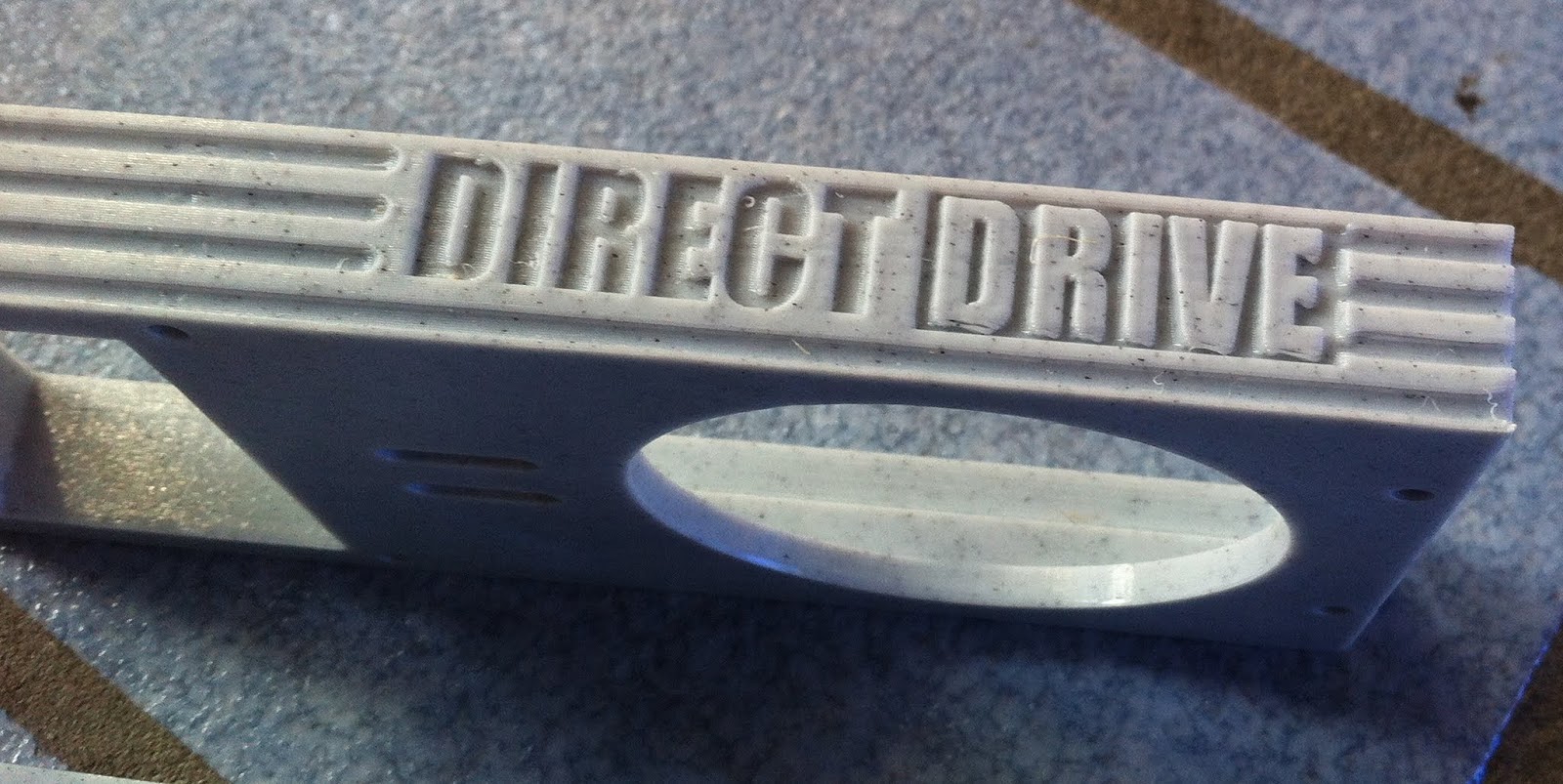
I also started doing printability experiments with various orientations and types of 3D text/graphics on my setup/materials. I have always thought a lot of designers went over the top with text and logos and greeblies, and so I have long resisted spewing badges all over mine. One thing I will ALWAYS do is to release a complete set of badge/text-free part files for every blaster. But I at least want to know the limits and the results of printed-in badges, for more subtle and boring things like model/serial/build date tags if nothing else. So time to do some test parts.


I had had this DIRECTDRIVE badge thingy in mind for a while and it tested both positive and negative text oriented on the side of a part ortho to the bed, and it has some big horizontal overhangs and some fine little features... Good stress test.

Then there's this one:


Tacky and OTT perhaps, but at least one of my personal Things needs a proper snipe at DC motors plastered on the side. I have fond memories of a certain rental Yale reach truck at work that was, like my blasters, fully brushless, and had (you guessed it) these big, tacky, over the top AC POWER badges. These covers make a good test case for bridged negative features facing the bed, and are the most likely place to put "nameplate" type stuff. A lot of people do it on FDL-3 sideplates, but the outside surface on those is a top layer.

Liking the results of both. Pretty much as it came off the machine, haven't even picked out any strings or blobs yet...


I'm surprised how well printing this doesn't fail. Sometimes, FDM is PFM.


And these come out nice and sharp too. Be mindful of elephant footing if you're going to do these sorts of things. Would really look nice as a multimaterial, obviously, if you wanted to do something less subtle like put your username there.


Silly stuff mostly. But the resolution is better than I expected and could easily resolve smaller text.

Wednesday, February 26, 2020

S-Core Firmware 0.95 - Home bolt with flywheels turning at low speed; more robust and snappier speed-based feed control.

Link

Changes:


  • Home bolt with flywheels turning (at default low speed)


The previous selftest routine reset the bolt at startup with the flywheels stopped. Occasionally, such as in the case where a stoppage or debris is present or the bolt is not homed but a loaded mag is present, this would mash something into stationary flywheels.

Now we wait until after the flywheel drive rotation check and run the wheels at low speed while homing to spit out anything that is accidentally fed. If something is fired inadvertently during this procedure, it is barfed out at about 36fps, so this is safe - assuming you have an ESC firmware with default minimum speed, which you should.

  • Improve speed-based feed control

A series of consecutive in-range tach readings (the number of which is still a build-time setting) are now required to initiate firing. This removes most possibility of enough randomly in-range pulses being received during the timeout window to fire when a drive is not actually at speed. This might happen during a stall condition while tach pulses may be clipped by start timeouts and/or there may be motor vibration which is capable of creating in-range tach pulses.

Offset margins and such have been revised slightly and control is a good bit snappier. Some perturbing of these settings may be called for to fine-tune velocity consistency, but it shoots pretty damn nicely with my Emax equipped primary.

03-04-20 Update: I have hotfixed some configuration parameters in this release. Posted as a Google Drive version, so should be transparent.


  • Set maximum flywheel RPM back to 25,510 since 26,000 is a deleterious overspeed for the Hy-Con and resulted in a decrease in mean velocity and an increase in velocity spread.
  • Make STC settings a bit more conservative since while it got consistent velocity at 50/25, how I had it set may have been edging toward not getting max velocity in lieu of snappiness in a few cases. This does expose the SimonK mid-speed transient response bug more as a slightly more delayed followup shot at certain speeds, but that's OK.