What the hell is the purpose of a concave flywheel profile, anyway?
(Be warned, theory ahead, but there are some cool things later on!)
Some would say it is to "support" the dart as it is deformed during contact.
Some would say it is to "get more contact area".
Others would note that a dart at rest is round, and if you smash it between cylindrical wheels, you don't get a uniform distribution of deformation, or normal force against the wheel, which is linearly related to deformation. You get a large spike in the centerline and a rapid decay toward the outside. Now this is the correct answer.
So can we go more basic than that? What is the purpose of flywheels? Well... To accelerate darts. With what force? Friction, dynamic friction. And whatever the coefficient of friction is in the system, the friction force is directly related to the total normal force on the contacting surfaces, and that is why we're deforming our darts with flywheels, to create a normal force against the flywheel surface. What do we want to get more friction? Well, we don't have the faintest idea on how to increase the coefficient of friction beyond what we have now in a practical system. That leaves the normal force. We want more normal force.
Now, concave flywheel profiles have so far proceeded in a rather "do it by feel" direction to my knowledge. It's pretty much a "Well, that oughtta fit the dart better than a flat one" type of deal. That the SSS format mounts the flywheel onto a motor shaft with a press fit, and flywheels must be a machined part which is not too easy to experiment with, does not help the matter at all. Profile geometry has lagged in its development IMO.
In particular there is a bit of philosophy I suspect of being misleading, and that is the focus on radial normal force. There are a lot of mild-concave profiles out there.

This is actually me CADoodling some large-diameter ideas prior to that spark, and what it is, is an excellent example of a mild-concave flywheel profile. You have probably heard me use that terminology, and specifically what I mean by "mild" is that the groove radius is greater than the root-to-root clearance when installed in a cage. As a result, the generating shape for the flywheel surface, which is also the shape of the resulting gap between them, is an intersection of two arcs that looks like an American football. Usually the endpoints of the "football" are off in the distance to the side of the cage and already get wiped out by the rim width of the flywheel. With SSS family parts based on compatibility with the old Hasbro 43.5mm center distance, there is further severe truncation imposed by the clearance in the cage or the blaster it is supposed to go inside. But you get the drift - with Artifact and Hooligan and especially BlasterParts and CC flywheels, you're forcing a round dart through a profoundly football-shaped hole. Seems right. Right? Isn't that what you want to do to a dart when there are two flywheels? We're applying a deformation in one direction. Right?
I'm gonna take a big leap and say that this is very wrong. We're not (necessarily) dealing with a deformation or a normal force in one axis. The normal force we are worried about is normal to what, exactly? Not some arbitrary axis going horizontally through the dart, ortho to it and the flywheel webs. No no no. Normal to the contact surface. Which can be and usually is curved.
So there's key element one, we shouldn't be throwing away the horizontal (parallel to the motor shaft) components of dart deformation and resulting force against the flywheel surface. Dealing only with the vertical component of the normal force is a relic of the cylindrical era, when the horizontal component was always zero.
Key element two is fairly obvious in my book. The whole reason to optimize profiles is to optimize the normal force distribution to achieve the greatest area under that curve with the minimum peak deformation. Deformation has consequences namely dart incompatibilities (n.b. people have had catastrophic results and lockups when a super high crush SSS setup is accidentally fed a FVJ dart) and higher shock loads due to the dart tip. If we didn't need to worry about that, we could just keep cranking old cylindrical flywheels, which have that deformation and force curve I mentioned with the giant peak in the center, as tight as we need to get the total normal force and thus grip we want, but clearly that is not going to end well. If we want to minimize the max deformation at any point and apply a given normal force over a given contact area, then, the best case is a perfectly flat force (and deformation) curve. We need to be crushing the entire dart surface uniformly.
(Note that DrSnikkas seemed to have the very same logic with flywheels that are also quite high envelopment, though I haven't had access to loose uninstalled ones to measure and know what the groove radius actually is.)
Key element three is about envelopment. We want to contact as much of the dart surface as possible with the flywheels. Not because "contact area" is itself worth anything, but rather because once again, it reduces the deformation needed to achieve a given area under that force curve. Or, maximizes the area achievable given a minimum flywheel gap.
And here is where all this logic is going.

This is a model of a high-envelopment large format flywheel showing a preliminary groove profile. It is 42mm root diameter, 4.5mm (9.0mm/2) groove radius, and 49.5mm OD, intended for a 51mm center distance cage.
The design principle is (somewhat erroneously?) describable as hydrostatic compression at the system centerline, i.e. the projectile is subjected to a uniform radial deformation. Instead of forcing a round dart through a rectangular or football-shaped hole, we force a round dart through a smaller round hole. Why a round hole? If you apply a uniform distributed load to the surface of a round dart and it elastically deforms under that load, it doesn't squash flat, it stays round. Seems obvious, doesn't it?
Here's a quick assembled cage render of another iteration of Hy-Con with suboptimal envelopment using some low-res meshes. You can see that generating circle appear out of the woodwork, broken only by the chamfers on the edges of the wheels to guide in darts and prevent the rims from being a pinchpoint.

This is another 9.0mm iteration BTW. I decided to initially back-off to 9.5mm root-to-root and corresponding 9.5mm/2 groove radius in the real world prototype. We'll see what that does on the chrono and go from there. It has way more envelopment than anything that has ever existed before.

And this is the 3D printable, minimalist prototype cage and printable wheels (very distinct from the version that would be machined, other than the profile).

Meant for no blaster - its purpose is to verify that I am not an idiot, and that the geometry works, feeds, doesn't jam horribly, shoot sideways, reduce darts to a cloud of nanoparticles, generate a black hole, or anything else undesired. Then I will get to designing this into something bigger. Oh, do I have plans for this little number once it is nailed down and working.
So enough theorizing and renders, here are the very first parts I received today. Printed by dkdavid721. PLA since this won't see service. It is split down the center of the bore to avoid printing overhangs. Pieces will be Devconned together.

Note I have long been averse to printing in nerf and I am finally starting to turn around on that with recent demonstrations of its viability. Some combination of realizations about design for it, and improvement of the technology.

41.5mm root, 50mm OD, 9.5mm groove generating diameter, 14mm thickness.
Comparison of OD to Hasbro HIR flywheel, and a SSS flywheel (Artifact V1 fullprofile serrated). These are big.

Okay, someone's gonna comment on that. Why is this a large format cage? Well, I am done with SSS format cages. It isn't about the limitations of the envelope so much as the limitations of the crappy, flexy stock blaster parts they get bolted to, so my intent for this is not to ever install "into" a stock blaster (though perhaps some version of it could be appended to a piece of stock blaster to replace the whole shell/cage mess up front). Secondarily, lower rotation speed and NVH, which once freed from the stock envelope is a gimme. And third was a simple matter of motors. This uses outrunners. Without that, I could not get prototype wheels printed without them self-destructing. Also, I am moving to outrunners in general. Better packaging, no shaft mounting. The speed capabilities of available, favorable motors dictate large wheels to have enough surface speed to support dynamic friction at useful velocity. So that's the way it's being done.
Prototype cage from feed end. Notable features here: 14mm bore, and low-angle feed ramp with 19mm entry diameter.

The 14mm bore is a sort of self-evident direction for cage design when dealing with high envelopments. The entering dart must be constrained to the correct position to avoid the flywheel rim pinchpoints. I have also had more messy or initially yawing Artifact Red (15mm bore on Gen2 and later) shots in combat than I like that seem to be related to rim pinch. Better round control is better, and it just seems like a good starting point. It isn't as tight as a classic DrSnikkas style tightbore and shouldn't do the negative things a tightbore does, but makes flywheel design a LOT less compromised.
The low angle feedramp; well, I don't know why Artifact and many other cages have such steep, sharp ramps that appear to have been made with an 82 degree countersink cutter. Is it really that big a deal to cut a nice gentle ramp when it's already on a CNC mill? I guess a bit more cycle time than the countersink cutter.
Flywheel cavities on the protocage are closed on the outboard end for printability of that outside bore half piece, this is possible since the flywheel can be mounted to motor and then assembly slid in and bolted down.

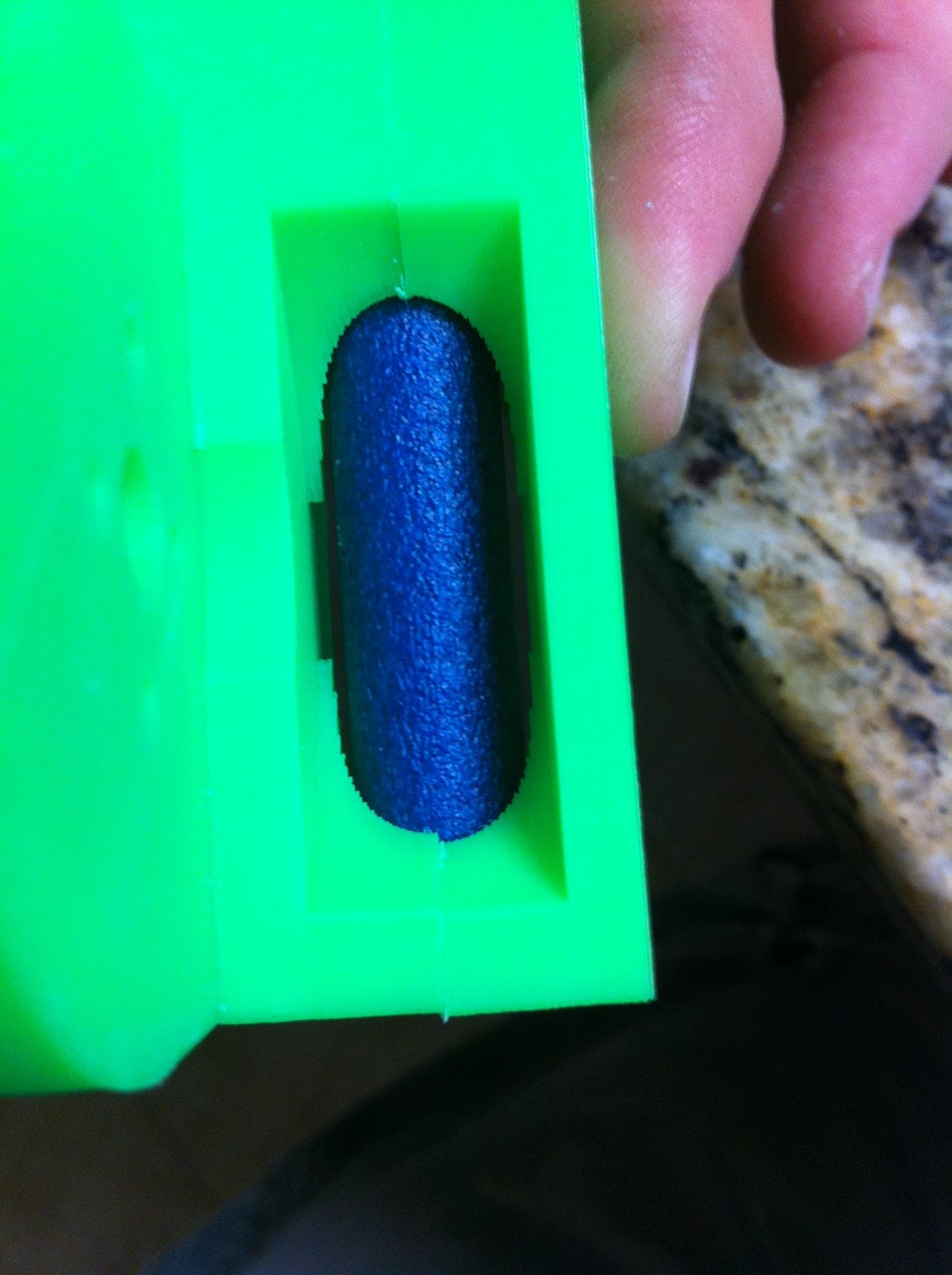
Here's the circular gap now visible in reality.

Putting a dart in there shows the hydrostatic contact principle quite clearly.

Look what happens to the hole in the foam! Not quite perfect since the rims have that chamfer.

Motors: Turnigy Multistar V-Spec 2205, 2350kv. Big brother to the stock FDL motor. Electrically a serious bit larger than the 2204 FDL motor. Rated to do over 400W continuous! We'll see how these start up. I didn't want to overkill things with a giant motor quite yet, because if we can get away with less current and less battery and less controller and less money, that's good.

Installation in flywheel: My flywheels have a bit more pot depth than a FDL wheel, motor ends up damn near hidden inside. Just the last 6mm of the stator base sticks out.

Test fitted to cage: Axial alignment looks real good BTW.

You can see how much motor stickout on the back of the flywheel there is in this image.


Threw a dart through here for an image.
Back side of a flywheel. A bit printy, and may have to be adjusted by hand a bit to bolt up completely straight and true to the rotor flange.

Hasbro HIR flywheel versus Hy-Con flywheel. Around 2mm less root diameter, and 3mm greater OD than the former.

So there it stands. I'm waiting for more ESCs and some hardware to arrive and then it's chrono time.
Wow, cool Design! Have you experienced overheating Problems with this Setup? Seems kinda closed up.
ReplyDeleteNope, stays cool; and motors in the modern Hy-Con are almost completely nonventilated. Wouldn't be too big a deal to add some ventilation (vents in the cage to match the stator base vents, and angled passages in the flywheel web to draw air through the other side) should a future motor option turn out to have more losses and need it, but the Vspecs never do.
Delete