Thursday, December 17, 2020

T19 - New full length breech; iFlight Xing-E 2207 and 2306 motor support; experimental 9.0mm gap wheels and cages.

The files named by the headings in this post are, as of the publication of this post, added to...
 
 
...in FreeCAD .fcstd source, STEP solid model, and STL mesh format in the appropriate directories with the appropriate extensions.
 

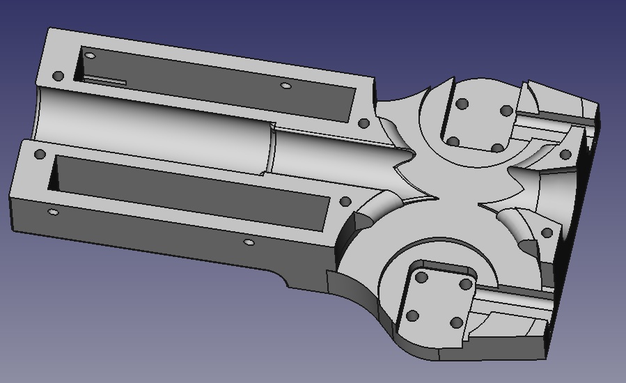
T19_FullLengthBreech_Gen2


A redesigned full length breech. Accepts most if not all superstock standard full length (12.7x72mm) magazines.


Uses the same T19_FullLengthMagRelease and T19_ControllerCovers as the original style breeches did. Uses the same hardware:

  • 4 * 6-32 x 1" SHCS (Controller covers, top)
  • 2 * 6-32 x 5/8" SHCS (Controller covers, bottom)
  • 4 * 6-32 x 5/8" or 3/4" SHCS (Cage module to front flange)
  • 2 * 6-32 x 3/4" SHCS (Rear flange to drive cover)
  • 2 * 6-32 x 5/8" SHCS (Rear flange to drive housing, center 2 holes)
  • 2 * 6-32 x 1/2" SHCS (Rear flange to drive housing, lower 2 bolts)
  • 1 * 6-32 x 2" SHCS (Mag release pivot; shortened)
  • 3 * 6-32 x 1/2" SHCS (Top rails to breech)


The old stock-blaster-style overinsertion stop methodology using the external ridge on mag bodies is eliminated and the overinsertion stop function is provided using the top of the feed lips as with the short dart breech. Accordingly, the magwell can now be angle-cut for aesthetics and ease of loading, and flared for ease of loading, as is the case with the short breech. Original full length magwell dimensions are retained. The fit is intentionally loose on many mags as it was before, for drop-free handling with most mags, and compatibility reasons, due to the large tolerances of this mag format.

The geometry at the front of the feed path has been improved.

The mag is now slightly further from the cage. The thin front wall is no longer so thin behind the cage flange. This allows a compound pre-ramp.

The thicker wall with ramp also prints cleaner and reduces the risk of burrs in this critical area.

The front halfpipe's edges have received a larger radius than the previous design and the oncoming lower edges meeting up with the mag body are now at an oblique angle to reduce the presentation of any sharp or tangential oncoming edge/surface at the advancing rounds.


Similarly, the rear of the feed path has received particular attention.

During the feeding process, the last event that must occur within a fraction of one cycle time as the bolt fully opens and clears the mag is that the rear of the topmost round (which was just being held down by the bolt) must rise up and seat in front of the boltface, ready to be pushed forward. If it bounces or snags slightly on anything, the bolt could contact it in the wrong position or miss and pass over it entirely.

As such similar to the front halfpipe, this now presents an oblique ramp but due to the even greater importance of this area (whereas the front of the dart has a much greater time to seat), it is compound.

Note that the sharp edge of the halfpipe end is so because it is a trailing edge.

Trivia: The caliber name 12.7x72mm Hassenfeld is a nod/acknowledgement to the Hassenfeld Brothers, founders of a like-named company, which would eventually go on to pioneer this caliber in 2005.


T19_TopRail_NewFullLengthRearSeg


The top rail rear segment for use with the Gen2 12.7x72mm breech, which is slightly longer than the old. Not much to see here.


Hy-Con-Delta_Main_iFlightXE_9.0_ready;

Hy-Con-Delta_Main_iFlightXE_9.5_only;

Hy-Con-GammaMajor_Main_iFlightXE_9.0_ready;

Hy-Con-GammaMajor_Main_iFlightXE_9.5_only


Hy-Con cage mains for iFlight Xing-E 2207 and 2306 motors. The same cage main supports both 2207 and 2306 variants. Only the flywheels differ between the two.

These motors have open stator bases and 16x16mm mounting patterns. They have no shaft end protrusion beyond the mounting plane and require no clearance pocket under the bearing, which is deeply recessed.

Fasteners for motor mounting are M3 x 10mm button head; shared with Turnigy cages.


The 9.5_only variants have the traditional Hy-Con groove filler geometry. They suit the traditional 9.5mm gap flywheels.

The 9.0_ready variants have slightly shaved groove fillers in order to restore safe clearance to the wheel profile with the 9.0mm wheels in the next section:


This modification by all means should be appropriate to use with any wheels, including 9.5mm and any larger special-application wheel - due to the radius on the filler edges in the original 9.5-minimum cages - geometry which is still the same and in the same place, only truncated a bit - this trim has very little impact on what is actually presented to the dart edgewise. I include the classical untrimmed version only as a matter of course and backup measure should any gremlins be discovered by anyone.

Also, there is no corresponding set of covers (or shaft end plugs) for these mains - they use the existing Racerstar BR2207S covers and plugs. This will very likely be the case in the future as well; most motors will be suited by either the Emax or the Racerstar cover/plug set. The Racerstar cover parts are universal to all presently supported motors and technically everything else could be deprecated.

The final little gotcha is an iFlight thing - iFlight has two main lines of motors, one of which is our relevant Xing-E. There are also a (just) Xing 2207 and Xing 2306 (without the -E). Those will NOT work. Those, in fact, are completely useless to me, because they use a novel "unibell" construction for the rotor and for aesthetic reason the outside of the rotor is not cylindrical thus I can't mount an OD-centric wheel on them. What we need here is the Xing-E, which is iFlight's slightly cost-reduced version with traditional rotor construction.


Hy-Con_iFlight_XingE_2207_9.0;

Hy-Con_iFlight_XingE_2207_9.5;

Hy-Con_iFlight_XingE_2306_9.0;

Hy-Con_iFlight_XingE_2306_9.5


Flywheels for these motors and cage parts. Print normally for Hy-Con flywheels i.e. 0.1mm layer height with optional 0.2 first layer height, 3 perimeters at 0.45mm or similar EW, rectilinear solid fill, 20% haxagonal infill, 8 bottoms 8 tops, random start/seam position. Nice and slow and clean, and get good fusion, and as always, whatever you do, don't underextrude. N.b.: Rotor OD fit may need tweaking for high thermal expansion non-PET materials such as ABS as always.


The 9.0mm gap option is the big exciting new thing aside from the 2 new extra-grunty motors - this is still semi-experimental, but is worth a bit more zip. I have, with the appropriate speed settings (remember to check maxRPM in any existing S-Core build as more than 25.5k will be required to reach critical with these on new ammo), seen 5-10fps more with used ammo and shot around 200fps with new ammo. Use only in concert with the 9.0_ready cage mains to ensure safe clearances! I have not seen many ill effects on accuracy nor dart decapitation rate, after a proper break-in period has been completed, and transfer layer has been established and stabilized.


The 2207 is a fairly long motor. Its corresponding wheel has 1.0mm of extra web offset and is 15mm thick, similar to the Racerstar BR2207S wheel.


In the future, this same or a similar wheel may be used to support the 2208 version of this motor in combination with a specific cage main with a circa 1mm greater mount offset; or else the 2208 may get its own +~2mm web offset wheel and possibly a slightly clearanced application specific cage cover.

The 2306's wheel is a standard, 14mm thickness design, albeit with a similar web thickness to the 2207 and Racerstar wheels - the 2306 is still on the long side versus the Turnigy V-Spec and especially the Emax RS2205S motors.


Aligning the rotor keys on these is a bit of a pain in the ass, unfortunately. Also, the rotor OD press fits are intentionally tight and the 2306 version especially is gorilla tight, so scrape/sand/deblip/destring the bore beforehand and be prepared, it's not SUPPOSED to slide on easily, it is supposed to be an interference fit. Do not thrust load the bearings, do not dare TOUCH that stator base when forcing the wheel on! It is often apt to use the shaft nut to help cinch it up the last few mm, but if it doesn't want to seat, do NOT keep cranking on it - check the key orientation and try again.

Below image shows how much the edge of the rotor backiron should be protruding on a fully seated wheel, by the way. Not much - about a mm, maybe a little less.


Effort and care building a Hy-Con system will be rewarded with a long-term reliable rotating assembly you will never need to mess with ever again for as long as the motor and its bearings keep on chooching, something which those other blasters don't fully achieve.

The motors are each available in 3 winds - the one appropriate for typical 4S (or 5S, or 12-16 cell NiMH, 5/6S LiFePO4, etc.) setups is the 2450kv. The 2750 would be ideal for (yes, I hear you; upcoming) multistage cages on 4S, and the lowest kv wind for high bus voltage (6S) single stage builds. As always, although kv and battery voltage have nothing to do with speed in closed-loop situations and you CAN use any combo capable of reaching the full range of speed setpoints you are using without running out of voltage command, using a needlessly high kv motor results in a less efficient system operating point and will only get you less torque, worse spinups, less battery life and hotter motors and inverters. More kv is not better.


Hy-Con_iFlightXE_ShaftWasher


Pretty self-explanatory - as with other threaded shaft motors optioned on the Hy-Con system, these motor/wheel combos have their own correct-thickness shaft washer to both take up unthreaded extra shaft length and to spread the clamping load.


Print any ways you like as long as it's got random starts and ends up 100% solid.

Be sure to check out the previous post back, on the build that validated all this stuff...

As usual, it was a super satisfying one to put together, and it feeds like clockwork and shoots lasers. Full length life!

Sunday, November 29, 2020

Adventure Force Sportsman internals, measurements, predictions

The Sportman has caught my attention. As I've said before, it's nifty - it does something that conventional wisdom has held to be impossible, and what's more does it well - and I'm looking for ways that it could be put to good use. 

So, today I'm doing a detailed teardown of the blaster. I'm doing this to get a good look at what's in there and what it can do, but this post should also serve well as an internals reference.

Extensive Adventure Force Sportsman reliability testing

This has previously been posted on reddit, here. I'm resposting on this blog primarily for the sake of having an archive with all of my work with this blaster in one easily-searchable place.

The Adventure Force Sportsman does something that conventional wisdom has held for years to be impossible: it feeds darts into a chamber through a hopper. Naturally, this raises concerns about whether this blaster can do so reliably. As a hopper-fed blaster, the Sportsman should be great for scavenging and for lightweight loadouts that avoid the use of magazines - if it is sufficiently reliable. That's a big "if," and that's what I set out to test here.

This is going to be a long, drawn-out post on a single blaster. There's a summary of the results near the start, after the jump.

Saturday, November 14, 2020

Thoughts on MLCC as inverter DC link capacitor

In quadcopter/drone ESCs post-BLHeli, it has bcome common to use arrays of multilayer ceramic capacitors (MLCC) as the DC link capacitance. A MLCC farm like this has become a familiar sight.


There is some considerable merit behind this. MLCCs have extremely low ESR and ESL, comparable to plastic film caps and any other type of non-electrolytic capacitor, and could do the job with much less capacitance than an electrolytic, which actually really suck at being DC link caps, despite always being used historically for DC link caps. More reading on the subject. Beyond that, an array of MLCCs on a board packages flat and thin and avoids dangly bits, and in terms of overall package length, the length of an existing lytic can added to the PCB is enough area to fit plenty of MLCCs.

On the cost front, it isn't too bad. A 10uF 50V X7R 1206 part, likely similar to the 18 parts on the above nerfish-scale board, from the vendor I usually use for MLCCs (Samsung Electro-Mechanics) can be had for 10 to 15 cents at this point in moderate quantity. If the Salcone-Bond whitepaper example cases are taken to frame a rule of thumb, certainly 18 to 20 such parts totalling 180 to 200 uF should suffice in most cases to replace the lytic(s) outright, at least in the current handling and bus ripple sense.

There are a couple of reasons I have been very reluctant about adopting either this strategy or a hybrid one with a smaller lytic and a handful of MLCC though, instead favoring the tried and true, dirty great big electrolytic, solution.

One is that MLCCs are brittle and sensitive to stress, whether mechanically induced (external forces or flexing applied to boards) or due to thermal expansion. And when these things crack, they often become shorted. High-current, deeply parallel MLCC farms directly across a lipo and immediately next to a heat source (FETs) give me pause for this reason - there are a lot of parts there to multiply the failure probability, they are attached to beefy, heavy (inflexible) copper planes, they get heated a whole lot at installation to solder them down to said planes, and they and the differentially expanding PCB are being constantly thermal cycled by FET heat in operation. If one dies, it likely causes a rather high-energy smokey unconfined failure, destroying the PCB and possibly resulting in combustion. I worry enough about the single big MLCCs that are across the battery on my ESCs and S-Core boards already. Is it really worth such fear? It is paranoia? I don't know, drones don't seem to be nuking ESCs all that frequently, I guess. Meh.

Another is that a pure MLCC solution has no "damping" the way lytics do. Small motor controllers normally don't have precharge setups for the caps at startup, and just get switched up with a huge inrush into the caps (and the familiar spark). Between the source inductance and the several hundred uF of basically-zero ESR caps, there could be spiking when powering up with just ceramic caps. It's like setting a car suspension spring vertically on the ground and hitting it with a sledgehammer. Pololu warns about this with their DRV8825 carrier boards, and their answer is to always have a lytic nearby on the same bus (as the 4.7uF 1206 input cap on the board). Advice to do similar things is common. So perhaps it is apt to use a hybrid solution at most, not purely MLCCs. Or perhaps a TVS on the bus could guard the FETs and logic power supply against overvoltage spikes sufficiently.

The third is that a MLCC farm to replace lytics turns 1 or 2 parts into 15-20 or more for a larger board, and a hybrid solution adds 4-6 parts and still doesn't completely remove the lytic cans that have to stick out somewhere, only make them smaller.

The fourth is that often, a huge surplus of capacitance is beneficial. The Salcone-Bond view of DC link caps assumes that they are solely there to source ripple current and stabilize the bus voltage at the input. In the real world, big lytics are often doing something else. In VFDs and appliance motor drives, they are much more a bulk energy store, since the input is rectified 50/60Hz mains and there are big valleys in the voltage that need filling in. In blasters, that's irrelevant, but they sometimes are doing the same thing to cache some local charge and prevent marginal battery and wiring conditions from causing the floor to fall out of the bus voltage as easily during a motor current transient (possibly to the extent of causing MCU resets and other woes). It's all the more important when batteries are NOT lipos (lipos are much more non-inductive than usual due to the stacked construction) and/or there is a long cable between the battery and the inverter, which appears multiple places in blaster design. Blasters can have much less optimal battery situations than RC stuff - just the matter that people play HvZ where/when there is snow on the ground and they are NOT going to be keeping a pack warm, for instance.

On the flip side, I do suspect my layouts with just the lytic at the end of the board are suboptimally decoupled and could benefit from a few MLCCs very, very near the actual devices in addition. And I kinda want to do a lytic-less board sometimes just for variety and to have an option that can be as thin as possible.


Edit/footnotes: https://www.rcgroups.com/forums/showpost.php?p=38006136&postcount=1220 https://www.reddit.com/r/Multicopter/comments/7nb2zs https://www.rcgroups.com/forums/showpost.php?p=41652761&postcount=16 https://www.rcgroups.com/forums/showpost.php?p=41660297&postcount=17 More interesting accounts of electrolytics and MLCCs and I wasn't surprised to see the exploded rail of MLCCs with a 1000uF lytic bodged in its place!

ACE-NX inline final tweaks, test boards on the way.

Last revisions: Fixed some potential shortcomings with grounding. Added a little copper island on the other side behind the phase wire pads on the edge. Stitched to the pad with 3 vias.


The idea here is to make the phase wire pad more rugged against lifting, this is common to use vias for this purpose in drone ESC boards. It also adds a small extra thermal area and mass to the lowside device.


I decided to mothball the LC Mini for now and focus on getting this beastie spooled up first. It will also be my potential dev board for the 6EDL04/ace.hex target before doing the mountable version.

Wednesday, November 11, 2020

ACE ESC: ACE-NX (inline wiring version) 1.0

Progress on the ACE-NX project has involved mostly ditching the bs_nfet_noninverting pinout and rethinking all the MCU pin assignments.
  • Gate, enable and nFault signals for the driver are all moved together and in order with the 6EDL04 driver pinout.
  • Throttle input uses ICP like Afro, not INT0 like bs_nfet. This kills some jitter and half the interrupt overhead associated with INT0. Also makes the throttle routing much better.
  • Phase voltage sense lines moved together.

However:


I also designed another board that was not what I was and am eventually intending (the mountable one), rather it's another ESC style unit. It's a combination of there probably being market demand for inline-wired boards like this, and me needing them for the T19 which I am not going to simply be replacing entirely anytime soon, and the fact that regardless of anything, since I DO want to start selling ESCs, I am either going to sell a modern driver-equipped board OR I am going to sell LC2s. So, it was time for the discrete drive to go and the LC2's beef shortages to be beefed, with the future of bigger motors and higher voltage DC busses in mind.


Which they have. The NX Inline is 1mm wider than the LC2 (26mm, same as Afro FS20), has beefier source connections on the lowside than the LC2, is busbar ready (use solid wire) and has significantly more highside device copper area/heatsinking even before adding a busbar.

Other improvements on the LC2 include revised FET footprints, all ISP pads in one place, plus the usual SimonK ready and warning LEDs, because blinkenlights. Also, the sense network may have finally received some due consideration. I tried to shove it to the opposite side of the board from all the noise sources like the DC bus path to the caps, and the SMPS. Something about sense networks is that the phase node, since it is directly connected to the motor, is mega low impedance, that's likely not what is going to receive noise. It's the node after the first resistor in the divider and of course the neutral. Those in my past boards had some long convoluted traces mixed in with the rest of the MCU-related traces and that is not good. With this one the resistors are right next to the associated MCU pin, the other ground resistor is directly underneath on the other side, neutral routing is very direct and the trace lengths are minimal. Will be seen whether these are cleaner starter-uppers than LC2s, it may just turn out to not matter.

Gate drive supply is from an AP3012. This uses a linear logic supply due to area and the lack of more good places away from sensitive stuff like the MCU oscillator and sense network to put a switching noise source without this board either getting bigger or being a pain in the ass. It is minimum 0805, as this is going to be the new general-purpose "not mini" ESC board and it is important that it not be a pain in the ass for either me or other people to make. Bootstrap caps, LDO input cap, boost input and output caps and driver 12V decoupling cap are all 1206. Also, it uses 40x20mil vias (mainly, for power stage reasons) which should eliminate fab issues as well with drill size.

Voltage rating depends on LDO and FETs. This can take a few different 40V devices and there are several 42 and 45V SOT-223 LDOs (the one I normally use is 40V) to correspond.

A bit of an erratum is that I post-schematic'd 3 0805 resistor footprints into this for pulldowns to ground on the lowside gates. Granted, every single FET/IGBT driver datasheet, board design and application note I have ever seen says nothing of the need for them, but to me, it just stands to reason that since the driver datasheets often don't give any indication that the output stage is NOT high-impedance with NO power to the chip, OR that there are any internal pulldowns on those gates, something bad could potentially happen at startup where the DC bus comes up a tad before the power rails to the chip do. So, I figure putting 100K or so (so as not to load the driver with much extra current) on the low sides to source will be a good safety measure against the chance that somehow, some gates are charged up when power is applied and cause a brief shoot-through. Probably just total design overkill.

Monday, November 2, 2020

S-Core firmware 0.97: Add nonvolatile user flywheel speed profiles

In the past I envisioned most blasters being run by default at full permitted velocity. If the game mandated less than the flywheel system's critical velocity for safety, that would normally be set with the tournament lock. Of course it would - if you can change it on the field, how could it ever be legal? However, by numbers, most games are quite casual and their playerbases quite mature, and they do not impose the use of the tournament lock, hence the typical usage pattern of adjustable-speed T19 in the wild is that players leave their tournament locks maxxed out and dial their blaster up on the chrono in user speed mode before playing.


This usage of the user speed adjustment mode with no means to save the resulting setting presents a number of problems. One, you have to dial the thing on the chrono every time. Two, if you shut down your blaster for any reason, you just lost your velocity setting. Three, you can't switch between canned velocity settings.

https://drive.google.com/file/d/1czPJ6wRAeR365x6zpS-CtlbzdjfZ84LU/view?usp=sharing

So I made a quick tweak that uses the selector position at boot time to choose a user-defined speed setting in EEPROM to either load (normal boot) or save to (speed config mode). As such, you can dial each in once and next time you want to use that setting, just put the selector in the requisite position before powering up.


Attempting to load a speed setting that is invalid or above the current tournament lock setting will throw a non-terminal Code 53, then save the current tournament lock setting to that profile, and begin normal operation. This will happen if you try to use a setting that has never been saved to (such as just after flashing), or if you try to use an old setting that is now higher than the tournament lock after lowering the tournament lock setting.

Saturday, October 31, 2020

Build: "ZombieStrike" T19E1 Shorty

This blaster is being donated to a local nerfer who lost a bunch of gear in a fire. He wanted a Gamma shorty and a variant of ZombieStrike scheme.


It has the usual control gear: S-Core 1.5 and a pair of ACE LC2.

It is fitted with Turnigy V-Spec motors, and I'm fixing to swap one of them out before it departs because of course one has some extra drag torque. These days with closed-loop feed control it's not like that even matters any more. But, gotta get rid of those dissonant spindown sounds. Turnigies sound so damn good among all flywheel motors when they are right.

 
Filament colors: Yoyi green, Makeshaper cool grey (may be obsolete) Makeshaper orange. The Yoyi green is absolutely as neon and great as it looks through a camera. Much like ZombieStrike green.


Thursday, October 29, 2020

Some electronics WIPs; motor drives and S-Core display module.

I have lately had 3, possibly 4, projects in the pipeline.
 
One is this motor drive, which has been internally called ACE-NX.
 
Key ideas here:

  • No more "ESC" stuff with the inline wiring, caps sticking off the end of the board, shrink wrap, ... Instead, this takes a more ground vehicle/robotics/industrial approach. Mounting holes, like the S-Core board. Phases and DC input wires emerge vertically out of the board. Cap cans are also mounted vertically through-hole (note big pads for thermal contact to solder those, since there is no relief on the pads for impedance purposes).
  • The idea with the packaging of this is to design it into future blasters rather than to fit existing ones, since now there hasn't even been a supposition of using off the shelf drone ESCs in blasters for over a year and that paradigm is kinda meh.
  • Return to the "sandwich inverter" bus structure and power device layout, from the ACE-LC1 and Protoverter.
  • Set up to be easily built as multi-voltage. This uses a 60V rated buck converter (LMR16006) to drop logic power off the bus. The powerstage can be populated with various 60V LFPAK56 devices to correspond and so forth for the DC link caps; hence this can support bus voltages up to approximately 10S, conservatively. The buswork is also very beefy, and this board would make a good super-low RDs(on) current monster using fets like the PSMN0R9.
  • Infineon 6EDL04 gate driver.
  • Has the S-Core style logic power input de-sagger/negative transient remover, albeit with a smaller 8mm cap footprint for the reservoir cap to save some space.
  • Has (optional) TVS across the bus at the power supply section to further safeguard the first DC/DC converter from spikes.
  • 12V gate drive level derived from 5V rail by AP3012 boost converter. Typical transient-robust approach to buck then boost, though I probably could get away with 2 parallel bucks instead, given the input filter on this thing.
  • Standard ICSP header, just plug in a ISP device and flash, no soldering to pads.
This was my first crack at it after being rusty and not designing any boards for a while. Also, I used minimum 0805 and some way larger trace/space than I could have, plus the big 20x40mil vias that I always used in my past boards like the LC2. Also, I tried out keeping roughly the bs_nfet pinouts and not shuffling my MCU pin assignments around to get the lane between that and the driver to work better hence a lot of contortion going on under the MCU. Still, it ended up at 25x62mm, the same width and shorter than a fully dressed LC2 with cap and wiring. That's promising, at least, but I will nevertheless set this file aside and cook one more PCB before this is over.  
Also worth mentioning the improved LFPAK footprints I'm trying out with this round (for hand soldering, not reflow obviously) and the return of the Afro's familiar blinkenlights. Anyway, this sort of thing is the future for my blasters, pretty much.
 
Next one, a simple discrete drive ESC style one with a 3.3mm (LFPAK33) powerstage, all 0603 except the Vcc bulk cap and bootstrap caps, SOT-89 linear reg. This should be a useful handy little thing. 18x40mm.


I made sure to use the MiniMELF compatible footprints for those bootstrap diodes this time round, the glass ones are so much less boring than SOD-123s. Also, Nexperia seems to have recently replaced the PSMN2R4-30MLH[X] with a PSMN1R6 part, which if you dig the Nexperia FET part number's logic, is a 1.6mohm nominal part. The 5x6mm device used in the ACE-LC2 is 1.4 (Hell, most of the losses are switching and diode conduction anyway at that point), and with the intended addition of solid wire or bars down those completely-unmasked bus traces, there should be enough cooling on them that this board can run all the usual 2205-ish motors without a hitch while also being smaller than LC2, Afro, Spider and friends.


And the last: a display module for the S-Core.


Of course one route is the usual Arduino style thing with Chinese OLED modules or LCD and be all modern and graphicky, but that is... simultaneously way overkill for just a blaster, and not kill enough to be worthy of a blaster, so in usual DZ fashion I took a more old school/hi-rel/vaguely industrial route with 5 cells of 0.2" LED 7 segment driven by a string of 74HCS595 chips. These things are slated to plug into the programming header on the S-Core board, which conveniently has power, ground, and 3 pins usable as digital I/O during runtime on one connector and avoids tying up the other ADC capable GPIO expansion connector on the board. The data line is bidirectional for that user button. As to that, this board and its design probably warrants another post so I will save it for that.

The possible 4th project is to replace the LC2 with a 6EDL04 driven, switchmode logic power, version of the same sorta-thing. With 0603 and 10/10mil it should be possible. I already mocked up a take on it way back on here, so no big deal.

The 5th is more unknown. Maybe a single-board blaster solution, maybe a driver-equipped version of the Mini above... or a 2 channel version with switchmode logic power. Or maybe a battery protection/management module that I have been wanting to do.

PSA: What if someone takes down their files?

https://creativecommons.org/licenses/by-nc-sa/4.0/:

You are free to:

  • Share - copy and redistribute the material in any medium or format
  • Adapt - remix, transform, and build upon the material
The licensor cannot revoke these freedoms as long as you follow the license terms.


https://creativecommons.org/faq/#what-if-i-change-my-mind-about-using-a-cc-license

What if I change my mind about using a CC license?


CC licenses are not revocable. Once something has been published under a CC license, licensees may continue using it according to the license terms for the duration of applicable copyright and similar rights. As a licensor, you may stop distributing under the CC license at any time, but anyone who has access to a copy of the material may continue to redistribute it under the CC license terms.


Most cases, are similar.

You, nerfer, have a moral obligation to the sanctity and continuity of our knowledge; which is the only true higher purpose or end that any of this stuff we do can ever achieve. Now, serve your duty to protect it.

You, designer, do not take your files down. Not only is it naive to expect the community to go along with your attempt to un-pull that trigger and un-shoot that bullet, but attempting to operate outside and beyond the terms of the (strictly irrevocable) license and pressure/guilt trip people into not exercising their rights under said license (like posting copies, because you don't want it up anymore, for instance) is not kosher in any way.

Friday, May 8, 2020

T19E1: Product-improving the T19 system

T19 really needed some TLC. Some had already happened, such as the new stock parts, but multiple things had stacked up that needed addressing:
  • Motor options currently extant needed multiplexing across the long and short barrel cages.
  • The now tested Racerstar BR2207S variant of the Delta (long barrel) cage and associated parts needed releasing anyway.
  • The short barrel (Gamma) cage just needed to be totally redrawn.
  • Short darts needed to be tested and natively supported, and one project to do that created a short dart breech and began evaluating Talon mags.
  • Electronics were, but eventually stopped being, in flux. The S-Core 1.5 board mounting pattern then needed to be added to the drive housing.
  • Top rails needed attention. A sourcing issue with the original part showed its ugly head and the rapidly multiplying number of cages and breeches also now required an extensible solution.
  • Everything needed to be reorganized, deprecated part versions axed, and everything concisely released.
  • STEPs needed to be generated for all old parts for which they were missing.
I started on this with the shorty breech and top rails, then the cages, and it ended up becoming a major cleanup and restructuring and a lot of small tweaks to the majority of parts.

The Gamma Major cage was totally redrawn (revision 3).


Emax RS2205S, Racerstar BR2207S and Turnigy V-Spec 2205 are now supported for all cages.

A blank version of the Gamma and Delta mains with all non-motor-relevant features in place have been created, for speedy and easy motor deployment by me, and there is a STEP of each blank for DIY motor options (You will need to design a flywheel and pick or mod the appropriate cover and associated bits).

The new Gamma features truncated groove fillers, as do all the new cages. Trimming nonfunctional regions of the groove filler, especially on the Delta variants, makes getting rotating assemblies in place less fiddly. The crown of the barrel has been radiused on all mains and covers to eliminate swelling of the corner and manual crowning of barrels. All formerly unbroken edges (mostly edges which butt up against another part to form one surface when assembled) that go on the bed when printed have been chamfered with 0.5mm to attempt to eliminate any "elephant foot" burr.

All cages have underbarrel rails as a standard feature. The Deltas have always had an accompanying rail with a nice round transition piece into the magwell front built in. The Gamma has had a rail option for a while too, but I don't think anyone has noticed its presence aside from Junior7 of CFDW who caused its creation.

As to short darts, this occurred.


This is an old school fixed speed, delay controlled, full auto only unit that was sitting around. Results were unexpectedly positive with Worker Talonmags. And what a handy sweetie little gun.


The formerly prototype short dart breech has been adopted effectively as-is as it needed no revisions. Elephant foot prevention has been added, new top rail bolt patterns have been added, and the new stronger 6 bolt breech flange pattern is also supported (note upper bolt holes). The flanges on this newly designed breech have been thickened versus the old full length part. A partial depth counterbore is provided on the lower bolt holes where the bolt head is exposed, for the primary purpose of full depth thread engagement with an off the shelf fastener and secondary purpose of having the bolt heads be less protrusive.

Uses the stock bolt. The fact that the bolt stroke of the stock 19 drivetrain with this puts the bolt tip almost into the flywheels might be a factor in reliability - the bolt occupying the space where a round just was at the top of the mag would help prevent stack tilting, and the excess motion would help to drag the rounds backward on the return stroke and keep dart tips from scrubbing on the front and sticking. So care will be taken if destroking the drivetrain is ever a factor, to see if that in itself raises issues (it is a variable in my last unsuccessful short dart evaluations not with a T19). Any case, combat trials pending, this setup blazes through mags just fine.

The caliber marking was only there originally as an experiment on the prototype short breech to see if I could get text that small and the answer was very much yes. Decided to leave it on because 12.7x36mmK is cooler than nothing or just "short" or something.


The short breech's mag release is designed to use the original mag release spring and fit the original spring seat and clearance pocket in the drive housing.

Now is a good time to talk about remaining work to be done. The original full length breech model was lost years ago along with grip baseplate and grip panels and no clean solid models of these damn things actually exist. All of them really, really just need to be binned and redrawn.

When it comes to the full length breech, that will get an angle-cut and chamfered magwell like the shorty version, and the use of feed lip tops as the overinsertion stop instead of relying on the ridge on standard full length mags, also like the shorty version.

However, I slapped a fresh coat of paint on the original style breech (de-elephant-footing, added the extra 2 breech flange bolt holes, chamfered some stuff that was sharp, added fillets to reduce stress concentration some places, added the caliber marking, the new top rail bolt pattern, shaved the uncomfortable bit of the magwell fence on the front of the magwell) and called it good for now.


With the grip base, not much reason to redraw it just to get a cleaner solid model, but the grip panels have always been a stopgap anyway and making some nicer smoother rounder grip scales for the 19 frame has always been on the list so there is that.

The drive housing now has the extra 2 breech flange bolt holes seen in the above parts.


This and the beefing of all new design breech flanges and cage flanges is a preemptive response to the unfortunate Naptown FDL-3 incident, as although T19s were already quite rugged, this particular joint was probably the weakest in the whole system. The extra bolts help spread out the load on the breech flange and give more thread strength in the drive housing.


S-Core 1.5 board mounting bosses have been added to the drive housing. A fifth nonthreaded support is in the center to prevent board flex when plugging in connectors. The S-Core board sits lower than the original boards did giving a bit more cable space, which will be welcome on the shorty setups where inverters have to be the drive housing. Elephant foot prevention has been added to the drive housing.


It has also been added to the spacer. Some corners in the spacer internal geometry are radiused. The edge in front of the limit switch has had a large ramp cut into it to address certain roller lever switches with loose levers and a protruding rivet potentially getting hung up, which has resulted in many spacers up till this having this feature ground in by hand when a certain switch was offending in this regard.


Perhaps the most visible external change of the E1 parts is that the new top cover has continued the "edge milled off at 45 degrees" chamfer motif from the Delta parts. Transitioning from the chamfered edge into stuff that cannot have a big chamfer there (for instance, cage mains, and anything to do with breeches since there are conflicting bolt holes) is inevitably either odd looking or a bit abrupt, but this above approach looks way more natural once assembled than it does just looking at the part.


New top rail patterns have been added to the cover. The top of the cover is now slightly thicker. The pocket into the cover forming the bolt rails and crank pin clearance has been smoothed out. The back part where nothing needs to be around the rail bolt holes is left solid all the way through as it is better to infill this with the slicer than cut it out of the model.

Now for the top rails. The original AIM Sports aluminum rails used on early T19 have apparently silently changed sometime between 2017 and now, which I didn't realize (it probably isn't a high velocity item so they would have lingered in the supply chain for years before selling) but in the end, I somehow ended up with a few of the same item that are clearly a slightly different part and have an incompatible bolt pattern. So... To hell with outside vendors for rails. The aluminum rail is nice, but after testing and experimenting with printing rails, that's not a problem. 5 perimeters 100% infill.

There arises a problem from the length of a full length top rail for the Delta cage setups not fitting on most printer beds, and then a further complication is that there are now 2 cages and 2 breeches, and there may be several more cages and several more breeches created in the near future.

Hence, this system. The rail is 2 piece. The front segments are associated with cages, the rear with breeches. This keeps things simple enough to deal with.


Gamma cage front.


Delta front.


Full length rear.


Shorty rear.

As a final option, there is a one-piece 3 bolt top rail for shorty breech, Gamma cage setups only. (It will also bolt up to a Delta and a shorty breech, since the same front hole is also present in the Delta cage, but isn't full length down the top of the cage, much like Deltas with full length breeches and aluminum rails.)


This rail exists because there are existing guns which may be converted to shorty, which have Gamma cages and bricktop drive covers with only the 2 10-24 threaded holes. This retrofits those setups without changing the cage main or the drive cover. The addition of one more bolt into the breech deals with the flexibility since the rail is polymer instead of aluminum. This rail is also a fine choice for these combos in new build as it removes a part and a joint and a few fasteners versus using the 2 requisite pieces from the 2-piece rail set.

The other setups are just too long to be reasonable to have one-piece top rails for.

Here's a configuration I suspect is going to be very popular among locals for comp and I already like based on my short dart testbed setup's compact size and wieldiness.


Priorities for the future are to do proper release notes for these parts, an updated build guide, and put up some electronics bundles for sale. (Don't get too excited and don't print preemptively if you know for a fact you can't or won't DIY your control gear and you aren't local to me. I really just can't build everyone a kit. I don't have time or desire to mass produce them.) Overall what this is going toward is leaving T19 in something of a final form for when the inevitable leaned-out vertical slim successor steals all the thunder and the design attention, but that isn't to say I have any intention of sunsetting T19 even then. It has a lot of stuff left to go. Lots of motors to try out, lots of local players to arm, lots of Stryfes, Caliburns and FDLs to eliminate. 2 stage .50 cal cages are coming very soon. Conversion to 20mm Mega is also a plan just for the hell of it.