This is another fairly quick one that will wrap up all the wiring/soldering (unless you have to put or change wires or connectors on a motor controller in the next step).
Tools:
- Soldering iron
- Knife
- Dikes or flushcuts
- Heat gun or heat source for shrinking tubing
Parts/Materials:
- 2 x femals 2mm bullet connector
- 4 x female 3.5mm bullet connector
- Battery connector to suit your packs, fleet, personal preference, etc. (shown, XT60 male)
- Bulgin C1300AA rocker switch, high inrush rated (Digikey part 1091-1013-ND) (N.b. This model switch is required by the OE stock with integral switch cutout.)
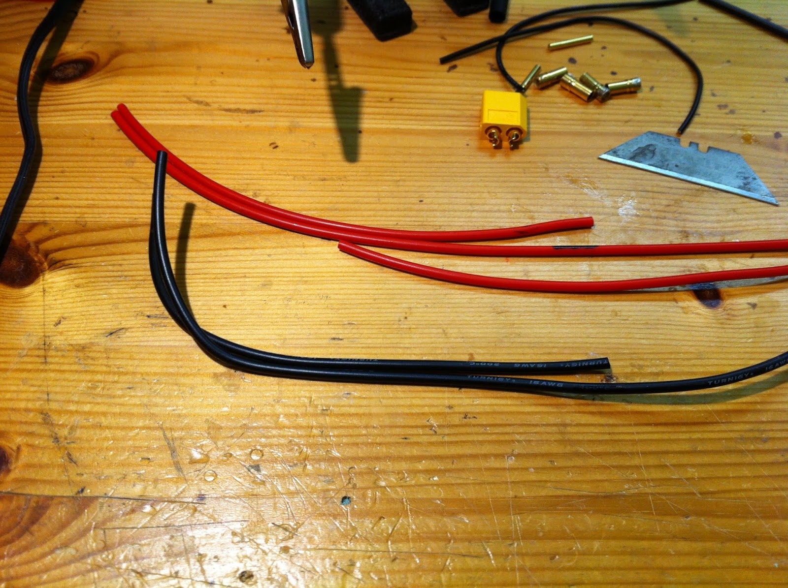
- Following silicone insulated fine strand (hi-flex, 200*C rated hobbywire) lengths:
- 14AWG or 16AWG, black (or other "ground" color), 19"
- 14AWG or 16AWG, red (or other "positive" color), 12"
- 14AWG or 16AWG, red, 8"
- 14AWG or 16AWG, black, 7"
- 14AWG or 16AWG, red, 7"
- 20AWG, red, 6" (shown as black, I had no red on hand)
- 20AWG, black, 6"
- N.b. Wire lengths for this prebuild are for the OEM stock. Switch setup and battery wiring will change with non-original stocks/alternate battery locations.
- Heatshrink (1/8", 1/4", 3/8")
- Leadfree solder
- Flux

Note on wire gauge: I would say 16AWG does it. 14AWG is overkill and 14 silicone is a clunky diameter with the thick insulation. I used 16 on this build.
Start off with the switch. Strip, tin, solder and heatshrink 8" red on center pin, 12" red on end pin.

Lay the 7" wire segments along the end of the 12" red (assembled with switch) and 19" black. Mark on the 12 and the 19 the position of the end of these wires and 1/2"-5/8" back toward the end for stripping.
Strip the ends of the 7" red and black and both 20AWG pieces. Do not twist or tin.

Carefully, without nicking the conductor, strip the marked spots on the 12 and 19. Careful blade use accomplishes this.

Twist on the corresponding color 7" piece and 20AWG, all wires pointed toward the end measured from earlier as shown. Apply flux. Solder these splices.

This forms the "squid" harnesses to feed both flywheel drives as well as the logic power module from the last post. The branches will split around the bolt motor inside the drive housing and go toward each controller compartment.
Be sure no solder points/spikes have formed when removing iron, clip off if present to avoid risk of punctured insulation and short in the future as these two high-current splices will coexist nearby. Heatshrink the splices. 3/8" tubing will likely be required.

Terminate squids: 16AWG leads with female 3.5mm bullets. 20AWG with female 2mm bullets.

Add some 3/8" heatshrink bits over the free end of both the 19" black (ground cable) and the 8" red from the switch (positive cable) to strap these battery leads together later. Slide those down temporarily near the switch to protect while soldering battery connector. Add two 1/4" heatshrink pieces to each wire and slide safely away. Terminate with battery connector. Position and shrink all those heatshrink tubes.
This is what the finished DC bus harness should look like.

No comments:
Post a Comment