
Oh man, where do I even begin... This was actively being developed about a year ago. I only recently happened across a cheap Zeus and bagged it and its cage, complete with flywheels and stock 360 motors, to replace the problematic parts in this from past experiments without spending much on it; and thus, I unfroze this thing.
At the time, Nerf Rival and its pioneering .90 caliber foamball format was very new, and the one question on everyone's mind involved hoppers and high-capacity bulk loading systems which the new spherical ammo begged for.
Airfeed, as popularized by outofdarts, Radiosilence187 and the "HIRricane" lineage, had not been invented/discovered yet. The focus was traditional paintball-style hoppers. Some prior art:
- Reddit user woodpiece converted a Zeus to fire .68 caliber Reballs (rubber reusable paintballs) using a gravity paintball hopper, a sweep pipe connecting the feedneck to the breech, and a powerfeed device made from half a Hasbro .50 cal flywheel cage.
- Mr. BadWrench (Donald Wester on Facebrick) attached a gravity hopper made from a plastic container or funnel to a semi-auto Zeus.
Sizing Up The Problem
It didn't take much screwing around to figure out that shear forces applied to HIRs (such as by a paddle moving the ball across a surface, as can be done with paintballs and the like) is a huge source of trouble. The soft foam tends to stick to such moving surfaces, and the friction force will cause the foam to deform and compress, increasing the contact area, which increases the friction force, which causes more compression and more contact area and more friction. The ball can easily wedge itself in place to the extent that huge forces are created. In testing of some of the following designs, the drill I used to turn the rotating assembly nearly ripped itself from my hands when a jam occurred, even when there was no physical edge or discontinuity where the jam happened, only a smooth surface. The violence of HIR wedge jams could certainly break parts and tear apart the HIRs themselves. There is no "muscling through it".
1" Schedule 40 PVC pipe was identified as an ideal feed tube/feedneck stock, permitting HIRs to flow through readily.
 |
| Fig. 1: Tangential feed housing |
Among the reasons for tangential feed was that the lack of any port or opening on the floor of the raceway allowed said floor to rotate. This rotating baseplate in turn avoided the application of any unnecessary shear forces to the rounds being rotated (only the outer housing part of the raceway itself presented such shear which proved to be minimizable to a useful extent); and thus there was no need for special paddle designs to avoid "running over" balls and jamming severely.
 |
| Fig. 2: Late iteration of the tangential feed engine prototype |
Next, short paddles 1/4" tall were added to the plate at its surface. This was more to provide the rotor with "texture" or purchase on the rounds than to absolutely force them to rotate, while hopefully avoiding creation of a pinch point at the feed port. Owing to the shear problem, force-feed operation was not yet in play - centrifugal force was to send the balls out the tangential feed port at a high rate once rotation occurred. This modification increased feed rate, but the paddles crossing the tangential feed port at a low and asymmetrical level tended to lift balls into the top of the port where a massive multi-round jam would develop.
Modifications to the paddles including shortening and chamfering corners did not address the issues. Presenting enough of a "speed bump" to stop the rounds from rolling on the baseplate was mutually exclusive with having them reliably file out the feed port and not be bounced upward into the top of the port, causing a jam. Feed rate was still low and gravity-like as well. Briefly there was a concept of short protrusions along the central cylinder to provide similar nonpositive drive without the lifting effect, but it was realized that this would cause rolling of the rounds against the outer case as opposed to circulation, reducing feed rate even more and conflicting with baseplate paddles (both at once may result in a wedging effect since the former causes strong contact of the round with the outside wall and thus friction).
 |
| Fig. 3: Backswept concave paddle prototype - looks cool, but failed |
Addressing the asymmetry/lifting and wedging observations of the previous 2 designs, radial paddles were next located to cross the centerline of the ball, to provide a centered force that would not tend to push underneath and lift the ball into the top of the feed port, nor to smush it outward against the housing wall and make it grab. The basic design was still centrifugal, non-force feed. This was found to cause pinch point problems at the edge of the feed port, and when the design worked and the balls finally circulated properly, feed rate was still low, as the rotating balls did not often successfully exit the feed port.
At this point I decided to abandon the centrifugal concept and move to force feed.
 |
| Fig. 4: Late iteration tangential forcefeed engine prototype. |
 |
| Fig. 5: Tangential forcefeed testing |
The diverter design, while crude, is accurate and smooth on the only places that it matters, and it ultimately worked extremely well for its core function. It was found that the same straight radial impeller blade ending at the center of the ball eliminated pinching of the ball at the diverter. When I loaded this design with balls and spun it, they poured out immediately in a close line, and never jammed.
However, there is a problem here. A loader engine is useless without a hopper, and this is where the "Halo style" design falls down. The diverter inevitably creates a pinch point apparent from the top down - such as when you have a hopper of balls on top trying to fall down into the blades sweeping through the diverter. The Halo itself has several forms of anti-jam doohickeys placed strategically at this location to prevent balls from landing there. See that little rod with black plastic beads on it? That.
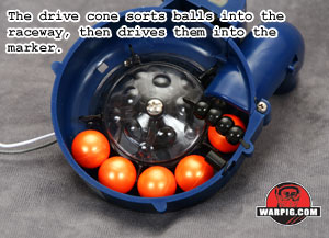 |
| Fig. 6: Halo (derivative) engine. Ewww paintball! Nah just kidding. |
I experimented a bit with that type of stuff but came to a quick realization: to a foam ball, ALL of those are a pinch point. No radius is large enough, no geometry magic. Either the edge is so sharp it bites into and grips the ball or so rounded the ball is rolled and squashed underneath it. There isn't much you can do in terms of forcibly splitting off a stream of highly compressible foam balls from a positive-drive style of rotor underneath a disorganized, non-symmetrically stacked mass of rounds in a hopper.
At this point, the radial feed testbed was junked.
A paradigm shift
I should take a moment to reinforce right about now, that the purpose of the project was not to develop the ideal loader immediately, but (1) to create a functional, reliable and combat-testable loader system capable of decent ROF without shaking as part of an exploration of the HIR system overall as a viable primary and (2) to establish the basic design concepts of HIR loaders as a platform for future progress.
I was considering making a simple gravity hopper with an agitator inside safely away from every wall, but at the last moment I thought of one last door to go through before giving up in such a manner: What if it didn't matter if the impeller caught and "ran over" the rounds? What if the shear problems were suddenly irrelevant?
With that in mind, I created this, and succeeded.
 |
| Fig. 7: DZ Rivaloader Prototype |
In its current iteration it has a 60 round capacity and the hopper is just the extended raceway housing with a pipe cap on it.
It is an axial feed design with a stationary baseplate and a 2 blade impeller. The housing is 4" ASTM D3034 sewer PVC.
This is the impeller, along with the self-locking spring steel pin that mounts it to the gearbox output shaft:
 |
| Fig. 8: Rivaloader field stripped |
All PVC fabrication here, expect nothing else. The central cylinder creates a loose one-round annular space for sorting.
The gearbox is a surplus item used in snack vending machines. The stock motor was replaced with a 60 turn RS360 out of ...a Zeus, and on 3S, it turns about 60rpm on the output. This is not fast enough, but it certainly works well for a prototype.
Down into the raceway without impeller:
 |
| Fig. 9: Empty. |
And with:
| Fig. 10: Reassembled. |
And more explanation of how that damn pin works. Bottom part goes through the shaft pin hole. It gets pushed flush when installed and clips in place with the little bend at the end. Easily removed with pliers for cleaning.
 |
| Fig. 11: Impeller pin insertion prior to installation |
The key is that the impeller blades are positioned about 0.8" above the baseplate. But.. that will run over the HIRs! Yes, that is the point.
 |
| Fig. 12: Design principle |
So? So what? Who cares. Why fight what wants to happen when it is easier to just pick one direction that it can happen in and make it safe for it to happen? The impeller blades run over balls and roll them over the baseplate. Frequently. Without harm to either HIRs or loader parts.
With more ammo in it:
 |
| Fig. 13 |
Mostly, balls circulate faster than rolling contact even in this prototype that made no effort to do so.
Feeding is semi-gravity. Is it a forcefeed? Kind of. But it isn't an agitator either. It isn't a particularly classifiable device. It will certainly put pressure on a static stack of HIRs but that definitely isn't how it does its best work.
Anyway, that wraps up the first iteration of the Rivaloader. Now I just need something to put it on.
The glue code
Something that became apparent is that in the hopper-loaded HIR gun system, there is a third distinct element that is required. We have a flywheel cage that needs rounds injected as per the user's trigger input, and a hopper that pours a stream of rounds out through a feedneck. How do we make those work together? Of course all of us thought "bolt" early on. Lots of people said "put a hopper and a RS pusher gearbox on a Zeus" without thinking the ramifications and engineering of such a device through.
I can tell you, from having tried it, it does not work. Bolts and HIRs are immensely, fundamentally at odds. This originates from the same qualities that cause them to need radically different hopper designs; and in the end, you either limit ROF drastically, or you have tons of pinch-type malfunctions.
This is my best working effort, a sub-caliber bolt that dodged pinches as much as possible and would still work as a flywheel pusher.
 |
| Fig. 14 |
 |
| Fig. 15 |
 |
| Fig. 16 |
 |
| Fig. 17 |
Topped out around 5 or 6 rps. Old RS box with damaged bolt tip was modded and hooked to that Delrin rod. The gearbox would have needed a spring-loaded bolt tip attached to prevent busted parts on a jam. I was holding it in my hand, in place of that.
The true answer is to use a continuous motion device. Now, woodpiece did something I found ingenious. He used a long sweeping pipe bend to turn balls (but not HIRs, just reballs) from a vertical feedneck into the cage, and a roller to feed them. I came in, adapted that to HIRs, and used a much more aggressive, positive, high-torque drive system with active braking, made from a hacked Stampede gearbox.
 |
| Fig. 18: Feed roller prototype |
Sector gear -> Feed roller. Cut the piece with the sector teeth off another broken pede sector, ground it down and screwed it on. Problem solved! Gear teeth make a nice aggressive serrated roller.
 |
| Fig. 19: Feed roller prototype |
Zipped up the gearbox shell as appropriate.
 |
| Fig. 20: Gearbox shell modified |
And mounted it up on the sweep pipe.
 |
| Fig. 21: Powerfeed device prototype |
Result, with another 60 turn 360 motor.
 |
| Fig. 22: Roller contact geometry inside sweep pipe |
Assembly now integral with the right breech half. Mount to cage:
 |
| Fig. 23: Powerfeed installation to cage |
Here you can see the stock gate linkage of the Zeus cage still in place. The trigger mechanicals are the same as an uncontrolled-feed full auto conversion on a magfed or airfed Zeus. Trigger just drops the gate.
 |
| Fig. 24 |
Trigger switch is tripped at the last part of the pull after the gate has fully dropped. This controls the powerfeed motor and is wired for AB.
When you pull the trigger, the gate drops, the powerfeed starts turning and grabs the HIRs coming down the feedneck and marches them into the cage at a controlled rate. On release, the roller and hence the rounds stop advancing almost instantly while the gate simultaneously blocks off the breech. The system is inherently fully automatic and cannot be easily cycle-controlled or made selective fire without round position detection, like all continuous-motion feeds. There is around one round at any given time in the pipe between the powerfeed roller and the cage that the gate is restraining at all times when not firing.
 |
| Fig. 25: Trigger switch |
I of course did this build into a zeus body for convenience, which is not my ultimate plans for the future iterations. Nor is the clunky redneckness of this thing to be carried forward if I can help it. But, I think I did fairly well for a build including vending machine parts, sewer pipe, and obsolete busted superstock detritus and costing actually very little at all.
 |
| Fig. 26 |
 |
| Fig. 27 |
 |
| Fig. 28: Powerfeed full auto HIR gun made from a Nerf Rival Zeus |
The Results
As it is now. Currently, powerfeed and loader are both running on the 3S Monolith pack that runs the stock motor Zeus cage. Good usable ROF.
And now trying 4 cell. Smokin!
Back to 3S looking at the loader churn away.
Something I forgot to mention: The loader plugs into the flywheel circuit. There are no separate controls for it, no switches, no eyes, nothing. It turns continuously whenever the flywheels are on. Or even just turning, since the motor back-EMF will keep it rolling from the fly inertia. Everything winds down and stops together.
So, mission accomplished. To this day, damn thing has never jammed. Not once.
Lingering problems at this point are 100% with the feed rate capability of the loader. It works GREAT if you shoot like you would in a normal game, but gets skippy and drops to around 6 rps if leaned on too hard. It needs to turn a lot faster, have something done with blade profiles to get more agitation on the top side, and maybe have 3 or 4 blades instead of 2.
The powerfeed device even in its prototype form is a great success. As long as you can keep balls going into the feedneck fast enough to keep up with it, it sure rips just fine. There is little to do but make it more compact and refined, and investigate using the roller drive section to turn balls through an angle - say, from a vertical feedneck straight into a cage without the bulky sweep pipe.
Another area needing investigation is whether this type of powerfeed unit can reliably push HIRs through long, perhaps uphill or bent, runs of feed tubing between the powerfeed and the breech. One of their inspirations was in fact the AGD Warp Feed. If they can do that, that opens up a whole new WORLD of possibilities for getting that annoying hopper down off the top of the gun. In particular, I would really like to use this tech to do a LMG build fed by a "box mag" (disguised bulk loader as an ammo can on the side). HIR seems super promising for this kind of stuff.
Even if I'm stuck with top hoppers, I am going to chase this venture farther and refine the tech. I like it. It's a hell of a lot of fun. Experimental superstock.
There was some guy that put a 380 size motor in a Stampede. He also made metal Stampede gear. Just saying.
ReplyDeleteYeah, well the gearboxes take 300 series motors and all of them are a drop-in.
DeleteThe plastic gearset is sufficient for this, there is basically no load relative to what this box is meant for.
I have yet to see proper gears that I trust long term for actual use in a Stampede (the best were the BattleGears cast bronze gearset which is still one weird manufacturing method choice). Not to mention the deficiencies of the crappy plastic gearbox shell and the weak little shafts that never got addressed. I have bent those shafts and egged out the bores in the shell back when i used these.
AEGs have potential but it will have to be at a later stage when they can be cheaply made to the correct standard. They call for steel gearsets and at least a cast alloy gearcase like airsoft. For now... Flywheel master race.
Hrmm, noice noice
ReplyDeleteLook at what ATS did in paintball. They were some of the first to do magazine feed & their at 85 had a forward hopper which fed into the mag which used little sprocket teeth to lift the balls into the breech to be launched by the bolt. Their select fire mech was also fully mechanical, not electronic. The complexity was also why they started at around $700 (Angel territory at the time) and went well over a grand for a fully kitted out one. Too bad they're no longer in business.
ReplyDelete