Thursday, June 21, 2018

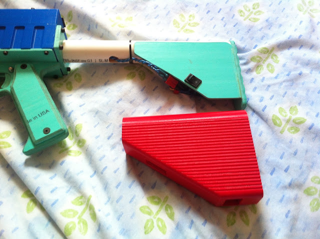
Project T19 Part 14: Stock and base printability and assembly fixes, new more durable flash hider.

Files

New flash hider model.


The old one was a hastily drawn part from the Model Pandora days, and was quite poorly engineered, having a sharp corner (stress riser) where the cylindrical bit met the flange, and other problems. One of those got taken out by a tree at NCFNC, so it was time for an upgrade. The new one is considerably beefier all around, has a thicker flange with counterbored fastener holes, proper fillets, better wrenching clearance for the bottom bolt, a blunter front edge to be kinder to any zombies crashing into you, etc. It is also a bit more proportionate.

Did I ever discuss that the flash hider is also a rifle grenade launcher? Uh, so, it's a rifle grenade launcher. Insert a Mega dart into it. Fire a .50 cal into the Mega and the two inelastically collide and proceed downrange with quite enough velocity to waste specials. The new one should support and align the Mega a bit better for launch.

Other fixes:
  • Both stock models and the stock base model have had the tube bore increased to 33.6mm for less grinding/sanding and much easier assembly to 1" IPS stock tubes.
  • Both stock models have had a 0.2mm thick membrane added over the stock tube hole at the front inside flat surface, making this surface continuous, so bridging is cleaner, and poses less risk of a crash.
  • The stock model with charge port has clearance improved for certain DE-9 connectors.


Sunday, May 20, 2018

Project T19 Part 13: Part Model Bugs Stomped; Core Visual Schematic

A super quickie:

The Rev2 models for the Gamma Major main section (enlarged phase wire channels), grip base (add clearance notch for the drive housing spring perch reinforcement thingy) and breech (trim the lower edge of the side cover mounting bosses) have been added to the Google Drive. Should be print, drill, tap, deburr, hand fit mag release and trigger axial play with file/sandpaper if necessary, and go.

Gen3 Hy-Con wheels now have a full range of gap settings from the old standard 9.5mm up to 11mm in 0.25mm increments. If you are concerned about decaps or trying to run at less velocity than 175-190fps, those should help. Remember that you probably will want to change your governor settings down from the stock 9.5 wheel 25,510rpm setpoint to match the wheels, even if you aren't trying to go subcritical to meet limits. Hy-Cons seem to greatly dislike being oversped.

Also, this should help you build a Core compatible controller:


https://drive.google.com/drive/folders/1lskje8W1EY8FvAvpWagquWdowgmAX9a8?usp=sharing

I have been thinking over the subject of PCB Core boards and also due to the Project FDL precedent, I have been getting a number of inquiries about assembled blasters and T19 wiring/electronics kits. I'm reluctant to say I won't do either of these flat out, but I just can't supply the world with T19 blasters and turnkey electronics.

I will look into the PCB subject and at least supplying that bit. My reluctance is due to the fact that within probably 6 months, new features will have been implemented and the hardware changed/added to. But at the same time, it's not like a couple dozen Core 1 PCBs would not go to good use.

Sunday, May 13, 2018

Chaotic Shortbus functional completion

Does anyone remember the Chaotic Shortbus? Probably not, but it's a build that's been on my mind recently. It's been several years since work started with, thus far, too little to show for it. As of the last update, this project consisted of a nifty concept, a sorta-ugly shell, and a pile of half-completed internals with vague plans for how everything would eventually fit together. There was still nothing that actually shoots, despite the fact that this build started in 2015. Since then, we've seen the end of the great motor drought, seen the rise and beginning of the stagnation of the Rival line, seen the rise of 3D printing as a widespread tool in the hobby, seen the rise of brushless motors, and seen the development of the Caliburn - but, at least as far as the Chaotic Shortbus is concerned, nothing worth writing home about.

There were reasons for this, mostly having to do with the fact that I wasn't confident in how to proceed in certain key areas, but . . . these were not really good reasons to shelve the build, in as much as waiting hasn't helped to make answers to those questions appear, resulting in a half-completed project rattling around and taking up space nigh-indefinitely - a situation which, I realized, was doomed to persist until those still-present obstacles are simply ignored and completion attempted regardless.

So, it's time to finish this darned thing.

Sunday, May 6, 2018

Project T19 Part 12: Flywheel drive tuning progress.

I mentioned a while back that I was having trouble getting consistent motor startups out of this one problem gun with its extra-stiff DC bus (and it's a T19, so it runs on 4S too). After perhaps 20 experimental SimonK builds, I think I have that squared away, and furthermore I am happy with what progress I have made on the wheel-drive front as a result.

Current SimonK build here - Afro NFET binary: afro_nfet_reschedule.hex also source for the Afro NFET, (note why I included the afro_nfet.inc file - watch out for board .incs clobbering settings, as afro_nfet.inc would do to MOTOR_ADVANCE!)

This is by no means a SimonK tuning workflow, or anything. Just the directions my experimentation took:

  • MOTOR_ADVANCE = 13

Previous to the last post about it, I had nailed down static phase advance (MOTOR_ADVANCE) at 13 degrees. One click higher or lower gave more rotor position losses at the transition to run mode, and the powerskipping to recover from those would result in less consistent spinups.

Next were startup mode parameters. Some N.b.'s about SimonK startup mode: Not only does that change the input filtering, but it forces maximum phase advance. This is, as far as I can tell, unavoidable, because BEMF zero-cross detection with only phase voltage feedback can only tell us which segment of the 6-step modulation diagram we ought to be in. We don't know where we are within that (60 degree) segment. So, applying an angular phase advance requires also knowing the speed of the rotor and that requires knowing the last few timings. If the speed is zero or unknown, it's undefined and all we can safely do is immediately slam the correct space vector at the motor. Now, something about these particular motors and highly advanced timing at low speed - that is very nonideal (I found out by setting MOTOR_ADVANCE to 30 in order to observe it in run mode) and makes VERY little torque. It follows; of course shifting things way too heavily toward the direct-axis current component at low speed. Thus, what matters to us is to enable timing control and set phase advance to something sane that (1) Is reasonably MTPA-ish (because, you know, we're trying to accelerate here) and (2) Ensures reliable sync holding, as soon as possible by quickly getting the hell out of startup mode:

  • ENOUGH_GOODIES = 6
What the fridge are "goodies" you ask? That's some dense SimonK jargon. Good zero-cross detections, good commutations, that's all. Stock setting is 12. This cuts the current-inefficient, sluggish startup mode window in half. Seems to have no negative impact, 6 commutations must be enough goodies for these motors to have stabilized a timing measurement for run mode. Also, how long we keep startup mode on appears to have no impact on run-mode reliability and current control considerations - it doesn't sound like these motors are managing to accelerate much in startup mode to speak of anyway.

With the change, acceleration is definitely more prompt. Stock SimonK can "sit there whining at 8 kHz" (it IS turning, just not making much torque and not increasing in speed very fast) for a brief but tangible moment before it really gets rolling. You probably know what I mean. That moment is startup mode staying on until there are enough goodies.

Also messed with:
  • START_DELAY_US = 0 (stock)
That adds blanking time before looking for zero-crosses during startup mode (there is also an algorithm that adds steps of delay on every failed start, which would auto-unbreak certain mistuned setups if you just keep trying to start the motor) - anyway; leave the above alone. You can try messing with it, but on my motors and boards, startup mode itself seems to perform well already and cranking this parameter worsened glitchy starts.

So that leads me to working with run mode, which turned out to be a source of some of the glitches.

The key thing here is current control. The back-EMF that is being measured for rotor angle detection is very low at low speed. Slamming too much phase current at the motor can cause too much noise to reliably follow. Sure, it MAY produce harder accelerations to crank the shit out of all the duty schedule parameters, but a harder acceleration that might follow a aync loss and powerskip and thus become a delayed harder acceleration (taking more time overall) 3% of the time, is flatly useless if we are trying to make a blaster more responsive. At the same time, there is saturation in the stator, so past a certain point it won't help as much as you think. And also at the same time, the current control in SimonK is not current control, it is a frequency-based duty (voltage command) schedule, so actual currents scale with bus voltage, and thus with my motor and 4S, it is already considerably more aggro with stock SimonK than, for example, a FDL drive on 3S.

Detour to overview of late SimonK duty scheduling:

* PWR_MIN_START (stock: POWER_RANGE/6) and PWR_MAX_START (stock: /4) set the endpoints of a "ramp" used in startup mode. Normally, PWR_MIN_START is all that matters unless you fail a startup (which like the start delay deal above, modulates more power within this "ramp" on every occurrence, which can help to auto-unbreak problem cases and get motors to at least run).

* PWR_COOL_START is used if a whole shitload of start attempts fail. This is normally set to /24, it is for locked-rotor protection and shouldn't be changed.

* PWR_MAX_RPM1 (stock: /4) sets the lower run mode duty limit, which is associated with TIMING_RANGE1.

* PWR_MAX_RPM2 is deprecated and isn't used anymore, I don't know why that is still there in the source. That was for the old versions, which shifted duty like an automatic transmission in discrete hard steps. Later versions do a ramp that is more refined.

* TIMING_RANGE1 (stock: 0x4000) sets the speed under which the lower run mode duty limit PWR_MAX_RPM1 applies, in steps of 0.25us per commutation step (stock=4096us). Above this speed, the main run mode ramp applies.

* TIMING_RANGE2 is unused, see above.

* TIMING_RANGE3 (stock: 0x1000) sets the ramp endpoint speed at which the duty limit becomes 100%.

* TIMING_MAX is the governor.

And my settings:
  • PWR_MIN_START = POWER_RANGE/6
  • PWR_MAX_START = .../6
  • PWR_MAX_RPM1 = .../6
  • TIMING_RANGE1 = 0x6000
  • TIMING_RANGE3 = 0x1000
Non-stock settings bold.

Logic behind these:

* We know we have a startable drive and not some random motor (stock SimonK is set up to reliably make any random PMSM/BLDC type thing that anyone might hook up to the controller start and run). Thus, there is no need for the startup mode ramp. Thus, it is disabled by PWR_MAX_START = PWR_MIN_START.

* PWR_MAX_RPM1 being set at /4 produces too much phase current at low (LOW low, like sub-300rpm low) speed, and causes glitchy sensorless operation, so this is chopped back to /6 resulting in MUCH more stable transitions into run mode and effectively no "unpredictable spinup" incidents. Also, it being /6 mates up smoothly with the PWR_xyz_START and prevents a hard step in duty from happening there (which is also a phase and bus current step and can result in problems with noise).

* TIMING_RANGE1 is moved back from 0x4000 to 0x6000. This just about compensates for the previous by starting the ramp sooner.


The difference between the problem drive with my old Model Pandora era build and the problem drive with the new build is night and day and puts the formerly buggy Serial One setup right back on par with or better than the Model Pandora on its preferred battery.

It also has the side effect of better current-efficiency and less heating during startup. The motors are definitely cooler after a series of 0 rpm starts.

The tune should be generally applicable to any 14-pole flywheel drive situation with maybe only a timing tweak for different motor families, and should have the impact of reducing the sensitivity of the drive to battery, wiring, motor and controller variations.

Project T19 Part 11: more parts info, turbo mode demonstration, drivetrain lubrication.

All locked down for combat test at this point. I don't anticipate anything happening, but the old reliable Model Pandora will be on backup duty. I have come to greatly trust that blaster.


So first of all I will hit some quick parts-related things that I didn't cover:

The top rail is a AIM Sports 12x0.40". Amazon carries them. Don't buy the other two thicknesses! (The mounting dimensions are different.) 10-24 socket head cap screws (not button head) are required to mount accurately. Again, watch out for that mounting hole depth in the cage! Too long screw can DENT THE BARREL, DON'T DO THAT.

The bolt motor is a OSM (available from StepperOnline) 17HS16-2004S1. M3 flat head (meaning countersunk) screws are required to mount, and a 10-24 x 3/8" setscrew for mounting the crank on the motor shaft. Shaft must be shortened - use drive spacer as a guide and cut carefully with a zip wheel.

Flywheel motors are Turnigy V-Spec 2205 2350kv. "CW or CCW version?" Doesn't matter, it's a bolt-pattern motor and we don't care about which thread direction of prop adapter is included, which is the only difference, because we don't use prop adapters. Again, very careful with your screw lengths around those stator windings, same as drone applications. M3 and M2 button heads. I use, don't trust these OTOH lengths entirely-- 10mm M3 (mount) and 6mm M2 (flywheel bolt) from Hobbyking, those are kind of soft steel and munchy so maybe not the best.


Flywheel motor controllers need to be able to run SimonK (not BLHeli, I do not use, do not like, and cannot support BLHeli, I have no idea what BLHeli would even do on my high inertia wheels and these motors - probably work, with careful tuning, but with an annoying startup lag and without the right sort of closed-loop mode, and you're on your own with the tuning part!) and have a large enough power stage to run these motors. This is not well defined, but any 20-30A controller should be safe. Look up the datasheets on your mosfets. Notably, I would personally steer clear of the Afro 20A RSM/20A Mini, which has the little SON mosfets and typically are Toshiba TPCC8076/8073 (same as the 12A Ultralite more or less!) rated for only 88A? peak drain current, which is kinda scary for running these with 4S on the bus. A hard lockup from speed is something SimonK does a very good job mitigating damage from, but it is finite, and NOT magic, and there's bound to be a little current excursion associated with that. I personally use Afro full size 20A, which is more or less the same board as the 30A fullsize, just with a bit less actual PCB area, and thermally derated. Perfect for our very transienty (but low continuous current, intermittent duty) app. The 20FS Optos come with Fairchild FDMS8018 mosfets, and that's one beast of a device for that size. Some of the 20FS, 30FS and 30RSM come with Toshiba TPCA8087 and that device seems OK too, though I only have a single pair of those.

Note I tune with Afro 20FS Optos and publish binaries of the T19 wheel drive firmwares for the afro_nfet board target. You need either a USB ESC flash dongle like the corresponding Afro one (if you're sure the SimonK bootloader is already installed) or appropriate AVR ISP gear to flash the controllers, a driver for that, and KKMulticopterFlashTool or just avrdude to do the flashing. If your board is not afro_nfet, you will need to download AVRA and build from source. Or ask me/send me the parameters you want if you know them (I don't expect you to, don't worry) and I will concoct a build for your board. Correspond with me if you have tuning issues/questions, too.


The preliminary Core backplane is built on a 2.0x3.0" Vector perfboard that bolts straight into the drive housing. The processor card is an Arduino Pro Mini (not Pro Micro, that's a different board!), you can use generics or Sparkfun first-source ones. You will need the corresponding FTDI USB serial interface breakout board (I got mine from Sparkfun) and drivers to flash the Pro Mini, but this is what I recommend, because it is rock solid and glitchless; trust me, onboard USB on a dev board like those Pro Micro things, is shit and I will never go back. The bolt driver card is a DRV8825 carrier board; all mine are cheap generics, which are fine, TBH. Other bits you need for the controller build and wiring are 100k and 1k resistors, a small electrolytic cap for the 5V rail, a ~220uF low-ESR electrolytic cap for the 8825 driver's DC bus, and male and female headers, lots of them for socketing both plug-in cards and making every cable connector. Note, your bolt limit switch connector needs to come out the back of the board where the big cutout is in the drive housing.

For logic power, I always advise a buck/boost converter, nothing less, for reliability (brownouts are not fun and can happen, there's a lot of current and noise nearby). I use Pololu S18V20F5. It's a big, expensive, overkill monster, but overkilling these things is not a bad idea, particularly the 35V input rating on that unit. A bad or overapplied logic PSU that shorts and puts unregulated DC bus into your 5V logic stuff will smoke your Arduino, 8825 card, and ESCs instantly and then you are out A LOT of hardware and money (including two increasingly-unobtanium Afros if you're using those) over a stupid fucking pocket change voltage regulator.

The schematic is coming; I promise. But if you look at the firmware... It tells you which pins on the APM board hook up to what. Wire em up. Not rocket science. Switch input circuit for trigger (both throws, so 2 inputs) and the bolt limit switch is a 100k in series with the MCU pin (for input protection) and then on the outside end of that, a 1k pullup to Vcc. Common terminal of the switch goes to ground. Pololu site tells ya how to hook up a 8825 driver - except note from the firmware the numerous pins on the 8825 card that need to be controlled in software in this blaster and should be connected to pins on the APM and not tied high or low. Then, you have Vcc and ground to distribute to every Vcc and ground pin, and raw DC bus to hook to the VM pin on the 8825 with the buscap from that to ground, set Vref on the 8825 to 1.0-1.1V, flash it up, plug it all in and away it should go. Unless your trigger cable is reversed and registers a constant down state when up. Then you won't finish booting and get the selftest growl and flywheel blip (turn it off and flip the trigger cable around and turn it back on).

Now to the part where "SimonK says 'get wrecked'":


This is a 22 round Workermag packed full, on turbo mode, set to 14.2rps and doing well. Shooting garbage darts this fast in long bursts can trip up the magazine on occasion, but the T19 is generally rock solid. The only time it skips steps is when it OUGHT TO skip steps, i.e. when a mag misfeeds catastrophically and a typical DC drive would have crunched the round into a huge folded mess (in which case, you let off the trigger momentarily, the bolt backs up and the malfunction normally self-clears). So that's kind of a thing, isn't it? Not quite the spam level of the DC drive FDL, but close, and it's still direct drive and brushless. Remember when there was skepticism about the stepper motor? Well, I guess there is still skepticism about the stepper motor, but I don't see why.

Now, bugs DID manifest and in this case it was a tribological blunder with the Production's all-printed drivetrain after some use. I didn't lube it at all, initially. I ran it dry like the Model Pandora (n.b.: the Model Pandora's bolt is PVC, so it has a dissimilar-material solution in place). The thrust faces on the side of the bolt and the inside of the spacer rails developed some minor galling with the symptom of random skipped steps after too long a burst was fired (and things heated up and got frictiony). Whoops; that was remarkably stupid to not lube that. The flip side is that (removing the galling and) lubing the drivetrain with white lithium grease resolved all problems and made general operation much smoother, and just messing with some scrap PETG prints, a little grease makes a MASSIVE difference in friction and makes galling almost impossible. Regardless, now that my attention is called to what's getting loaded heavily in this design, I'm definitely going to try out a rollerized bolt with some little bearings to eliminate the sliding friction at that one troublesome side thrust surface. Should help at high ROF and assist with maintaining tolerances without hand-fitting too.

Sunday, April 29, 2018

Project T19 Part 10 Developmental Release LInk and Rundown. Plus Inconclusive Buscaps and Startup Gremlins

First things first: Google Drive link to the T19.101 developmental release part meshes and some assorted firmwares.

WARNING: Developmental release means developmental release. This is for the curious, those who walk on the very edge and want to be the first kid on the block to have one of these at all costs, and for the benefit of those who want to adapt or hack parts of my designs, mainly. Sort of like SimonK says but intenser: If it explodes, you get to keep all the shrapnel. No promises and no support here - yet. That is coming soon. I promise.

Actually, the models all came out relatively final on the first print, and assembled into that first build without many trims and adjustments. But these are the known bugs:

  • Breech - Lower screw bosses for the side covers come too close to the cover's lower edge and will need to be trimmed about a mm back parallel to the cover edge to clear.
  • Grip base - Needs a grind on the top front edge to clear the mag release spring perch reinforcement in the drive housing.
  • Cage (Hy-Con-GammaMajor_Main) - Insufficient clearance in the phase wire channels for the heatshrink on the phase wires coming out of the stator. Needs ends of the channels widened adjacent to motor mounting surface.
  • Stock - may need some supports and/or spaghetti cleanup after printing a surface over air.
Some roughnesses and improvement areas:
  • Trigger and mag release axial clearances are tight - hand fitting parts is required!
  • Magwell fit - I erred on the side of loose for drop-free and compatibility with a maximum tolerance range of mags, but this feels somewhat sloppy, so I will be adding 1 or more magwell models with tighter fit in both directions.
  • Cage groove filler clearances on Gamma Major are tight with the 9.5 wheel, and the lead-side fillers serve no concrete purpose (they are absent on all previous groove-filler Hy-Con cages which work flawlessly) so could be removed anyway. If you mess up your flywheel manufacturing and fitting and have too much runout, you will hit the cage.
  • Bolt clearances in the drive spacer rails are a tad loose and AK-like - this doesn't affect anything functionally though.
  • I need to get those 10mm and even larger gap flywheels up as an option.
  • Stock and stock base tube sockets need a bit too much grinding/sanding for 1" PVC fitment. Ideally, just removing layer change blips should do the job.
  • Grip frame install into the channel in the grip base is tight and needs hand fitting.
A word on PLA: I have no experience with and can't support PLA for T19 parts. Do that at your own risk. I use PETG only. Most parts should by all means work fine with PLA, but I haven't and may never test with it.

Words on my slice/print parameters:

All numbers consider my 0.4mm nozzle and 0.2mm layer height.

Most unspecified parts I use 6 top and bottom layers, 3 perimeters, and 30% hexagonal infill.

Flywheels: 4 bottoms and 3 tops, 3 perimeters, 20% hex - this is a possibly PETG-specific inertia minimization which is plenty strong and stiff.

Cage main section: 3 perimeters, 100% infill. Hy-Con cages are very sensitive to stiffness in the motor mount section. Also, 100% cages are distinctly quieter even if you were to find that solid isn't quite necessary for stiffness.

Grip frame and grip base: 10 tops and bottoms, 5 perimeters, 40% hex. Don't skimp on these, they are how a rather heavy blaster is handled.

Crank web: You may want some more perimeters on that as well for shaft bore, setscrew thread, and crank pin thread robustness if using something non-PETG.

Preliminary words on assembly:

3mm motor mount holes for wheels and pusher, 2mm flywheel bolt holes, all 3.6mm 6-32 fastener clearance holes and 3/16" 10-24 fastener clearance holes need drilling to final size to clean out.

2.7mm 6-32 tapped holes need drilling before tapping to avoid difficulty - I use ~3mm with PETG.

3.8mm 10-24 tapped holes should be tappable as printed. Be CAREFUL tapping the front rail hole in the cage! Don't dent the ID of the barrel with the tip of the tap. It comes CLOSE in there.

3mm shaft pilot bore in the flywheel center is a relic and now an overconstraint. Drill that out slightly oversize. The rotor OD locates the Gen3+ wheels, not that shaft pilot.

Watch out for screw lengths surrounding motors, both the stator base to cage and the flywheel to rotor flange bolts have the potential to hit and damage the windings if too long!

Alright, time to stick an image in here to break the textwall and shift gears while the clutch isn't biting for a sec:


I remain unsure of this upgrade.

By all textbook and EE means, upgrading the DC link cap on an inverter should ONLY be able to benefit proper inverter operation and should be a safeguard against voltage transients. You CAN'T have "too much" of it. The DC bus is supposed to act as a stiff voltage source in the design theory of a VSI. Adding a larger capacitance with a lower ESR to it near the switching devices only assists in making that closer to true.

However, zero-cross detection sensorless is a finicky beast, and lacking feedback current control, parasitic bus impedances ARE a variable that affects phase current and could affect the performance of sensorless. With this build, I have encountered less consistent motor startups than with my other Hy-Con gear, and dare I say, the controllers with the 1000uF Kemets were worst at occasionally "misfiring" (with some red desync warning LED flashes while SimonK powerskipped and attempted to reestablish what the rotor position was) on start. This would occasionally cause a slightly delayed spinup and a derp shot. Controllers with the 220uF Haicaps that I have tested so far are also not 100%, but are slightly better (I have tuned the SimonK build and feed delays both to a state I am happy with using for now and has prevented all derp darts).

Component tolerances (sense resistors, ...) can't be ruled out as why certain individual ESCs might be more apt to have sensorless glitchyness at low speed. But at the same time, one aspect that stands out is that Serial One's 14AWG harness, very high rated switch, and present 1.5Ah Graphene all result in lower DC bus impedance (both resistance and inductance) than the Model Pandora's long 16AWG battery wiring, 16AWG squids, cheap switch, and Monolith pack. Perhaps it's that provoking the trouble. It's not unprecedented for this to be a variable to worry about. With Ultracage, some posts give cases where simply switching to a high end battery can make a BLHeli drive that previously worked completely freak out in a FAR more epic way than my perfectionist griping is about.


So there are 2 directions to go from here, if that proves to be the cause and not just a dud Afro board or two.
  • The correct engineering one: tune SimonK to work on this hardware with a very stiff DC bus. Changing various startup mode and ZC detection parameters, using high side PWM, or adjusting duty schedules (I did have some success with cutting the startup duty back a tad) might do the trick on top of the timing that I have been dialing in. Then, we can run uprated caps and have less voltage spikyness on the bus (safer for the mosfets), and be more tolerant of a wide range of batteries.
  • The "stop fucking with it; you had the damn thing working like clockwork before" one - avoid the overkill caps, and avoid the overkill batteries.
I'm gonna keep chipping at 1, but I am also going to consider the validity of 2 by trying a single-P Monolith on the same drive parts and software as a comparison. I'm perfectly happy with the performance of the single-P on the Model Pandora, and it is safe. It may well be that practically it is better and gives more consistent startups to have a slightly non-ideal bus voltage stiffness and perhaps even slightly duller best-case accelerations if that's what makes the sensorless voodoo happiest. Because what it boils down to is what feed delays you can consistently get away with, and right now, the Graphene-equipped Serial One is doing slightly worse at that, not slightly better as I expected.

Saturday, April 14, 2018

After-action report USF HvZ S18 and TBNC 5 - 2018-Feb

USF HvZ Spring18:

I was able to attend the last ~2.1 missions worth on Saturday (probably most of the combat in the entire 2.5 day game) - unfortunately not all of it, due to a combination of motherfucking work schedule and motherfucking slow I-4 traffic.

Mission 2 on Saturday was, to be honest, terribly designed. Humans were to move an objective (a giant teddy bear filled with 165 pounds of sand, and I am 100% serious) through 2 pagodas in USF's MLK Plaza and defend it for 10 minutes at each. The large Plaza was an Infested Zone, in which humans were completely disarmed and could NOT defend themselves, only evade zombies. The pagodas were sock-only zones. There were several circles of traffic cones in the plaza which were moved by mods at regular intervals and were armed zones, but only permitted 3 humans to be present. Zombies had spawn points at the edges of the plaza. Clearly, this sort of lazy, heavyhanded and agency-reducing game design, which amounts to not permitting humans to fight at all over a large area and requiring the vast majority of them defending to use a single type of weapon that was in short supply while zombies respawned and respawned and respawned and hammered them, resulted in a shitshow. There is a tremendous amount of discontent in the community about this mission and mods have deleted some threads on the facebrick groups, which is not a good sign at all in itself.

During this I held with the sideline group firing into the plaza from its borders, supporting the interior humans as well as we could. There was a bit of questionable human tactics here. Had I not been there to convince otherwise, everyone may have attempted to run in and join the sock unit or the cone zones, and we may not have had a persistent sideline group. Since the entire plaza disarms humans, the retreat at the end could have been a significant FUBAR without a sideline squad to stun zombies near the exiting human group. I'm not sure if players really comprehended that at any point. Also, one of the most viable tactics was to spawn camp the zombies and stun lock them, since the spawns were in an armed zone. Overall shitty design and poor excuse for a difficult slaughterhouse mission. There is a place for a difficult, casualty-inducing mission in games, but it ought to allow both humans and zombies to actually play the game as intended. That was just a bullshit mission in every way.

To USF mod squad's credit, the final mission was much better and involved defending multiple locations while data was retrieved, then returning the data to our NPC. This was a good hard fight but it was a well designed mission.

So onto the gear observations.

The Model Pandora T19, running 4S closed loop and 11rps ROF, was absolutely rock solid. Zero complaints with it at all. This was my first time running single-trigger control in HvZ, and it was a straight-up improvement under combat conditions, I don't miss manual motor control one bit. Closed breech and stepper direct drive feed reliability is absolute, with perhaps one time where I skipped some steps momentarily and then self-recovered. Velocity and range improvements with this system were also very nice; USF is a very open campus compared to the locations I played long ago, and the game tends toward ranged standoffs under which Hy-Con flywheel systems were excelling at dealing out hits. Hitting harder does also help enforce honesty, more people called their hits when I shot them this time than I have seen in past games running stockoid guns at lower velocity. I have not had any complaints from zombies about pain yet despite the high velocity and occasional engagement up close. Ammo use when engaging at range and overall is significantly reduced as well with the accuracy improvements; I was finding myself doing about half a mag per charge.

Waffle tip and generic Accustrike were the darts that proved themselves. I still prefer waffle outdoors at long range, since Accustrike is a bit more droppy. However, Accustrike is consistently grouping very well and its range is nothing to sneeze at either. In TBNC 5 the following day at USF BSN building, I had received my accustrikes from the TBNC group dart order of about 23,000 rounds and was running mostly those, which were able to nail lots of difficult shots on mostly-hidden players.

I brought one mag of Mengun darts to a mission for evaluation, since I have a large old stock of them that I have been saving. Unfortunately, these didn't hit shit at the 180+ fps the Hy-Con can put them up to; they behaved like streamlines and attempting to engage at ranges where waffle could basically point-and-click a zombie's headband down was just downright hopeless and hilarious; a sideways tornado of entropy going everywhere but the zombie who is now laughing at me. That is unfortunate, as Mengun has had a very low tip loss rate, good velocity retention, excellent flywheelability, and great foam and is also barrel-compatible to some extent. This isn't unexpected though that as velocity keeps climbing that ammo changes are going to be necessary and older darts are going to become inadequate just like koosh did around the 150fps high-crush SSS era.

One of my early adopters of Hy-Con, UF HvZ's Matthew Bregg, attended the game. Check out his blaster build Yellow Submarine sometime; it's a Swarmfire shell containing a Rapidstrike gearbox, a Hy-Con cage package with 20A Afros and an arduino doing some cool pusher motor/gearbox protection and select-fire stuff.


He was running a Protocage a while back and recently upgraded to a Beta Prime and Gen3 wheels, solving those waffle jams that the old non-groove-filler cages had. This was great to see the Hy-Con used by another player and to have 2 of them on the same field. Pretty cool to hear V-Specs firing up on SimonK and the snapping of darts going through coming from elsewhere in the formation.

He also gave me some newer red tip/black foam brick tip darts to try. I meant to get detailed observations but instead I wound up railing on zombies with them. So... Thank you for the stuns. They did well, comparable to waffle or maybe better, so I purchased a case and have been running sample mags time to time. Next TBNC field game will be the true test, but I am considering both them and waffle as my go-to range/outdoor dart going forward. Glue is also much better than the brick tips I had long ago, and better than waffle and accustrike clones these days too. Of note is that the brick tip design is unexpectedly flywheelable despite its apparent structural rigidity in the radial direction - when playing with a cage I was building rolling some darts through by hand it was clear that the horizontal layers actually get folded forward and inward while entering wheel contact, and that most likely happens in real time as well. The bricks have been shooting smoother and quieter than waffle on my Hy-Cons.

Unfortunate casualty of the weekend was one of my Worker 22 rounders, which seems to have been stomped on HARD in the chaos of the final mission's last objective.

I'm not sure if that can be repaired, it's smashed the fuck up and might be totaled. Probably just some bad luck, I have actually threw fewer mags to the ground lately than I used to notoriously do. Oh well, it's just a mag. Speaking of Worker 22 rounders, I am very satisfied with these. Absolutely recommended, 22 is a great number and I have had excellent reliability out of them. However, if you are a shorter individual or a chest rig user they are going to be awkwardly long. I'm tall and built just about like a slightly scaled-down Na'vi and I also use only belt rigs for mobility and cooling reasons.
I also did another UGA'14 style "rifle always" run this time around. I brought my WASP and holster to the game, but I never put it on, it was in my backpack the whole time. I never felt like I needed anything beyond the T19 and a few socks in case a Hunter went after me. The following TBNC game I only brought the T19 and my holdout Jolt. The T19 has so far been exactly what I wanted it to be, which was a blaster that can be absolutely trusted.

Friday, April 13, 2018

Project T19 Part 8: Quick Update (images)

T19.101 aka: "Production T19", codename Model Mo'ara


One-piece breech housing. New mounting patterns distinct from the symmetrical, narrow spacing Model Pandora breech bolt pattern. Vertically taller drive section pattern. Provisions for new flywheel motor controller location under side covers (which is only a cable space on the Model Pandora). Widely fenced magwell for forgiving loading. New mag release pivot design using a SHCS instead of a press fit pin. Unified aesthetics and smoothed handling areas.


DC link capacitor upgrade for 20A Afro motor drives: stock 220uF 35V Haicap, uprated 1000uF 35V Kemet ESY. Wimpy wimpy wimpy... HEFTY HEFTY HEFTY.


Controller with DC cap uprate installed with Gamma Major cage mated.


With side covers fitted.


Flash hider is carried over from Model Pandora (3-bolt muzzle device pattern is part of Gamma Major cage models by default)


Gamma Major changes include smoother externals, even stiffer design with reduced stress concentrations versus narrow-center Beta family, counterbored fasteners (excl. motor mounting bolts for a specific durability reason), tappable hole patterns for flashlight mounts, double-sided groove fillers, radiused user contact edges, and flywheel bolt inspection/torque check holes. Basic Hy-Con dimensions are adhered to, though <9.5mm wheel profiles will require a revision with slimmer groove fillers to clear.


T19 buttstock system uses 1" Schedule 40 PVC. Stock base with integral Masada-style sling mount using a SHCS. For lefty user, reflect model about axis before manufacturing, or install upside down if you don't mind where the screw head is.


Stock body is a battery box and contains a seat for the Bulgin 1300 series high inrush rated main power switch. An alternate version contains a DE-9 connector mounting pattern for internal charging of a hybrid cylindrical battery.

This is a 19-odd hour print. I started this chooching, went to work, came back with it still less than halfway through, had a very sleepless night while the Prusa chugged away, and had her done and lifted off the bed by 1600 today. Whew, thank you Eywa, for watching my silly machine and making sure this one didn't crash.


Collection of parts, including Production's totally redesigned drive housing and drive cover to be shown in detail later. A drive spacer is running right now.


The stock body showing switch cutout. Some pretty hardcore bridges in this part but did quite nicely.

Bug: There is a bit near the end where the stop for the stock tube is that is a SUPER hardcore bridge outright printing a big flat surface and a circular hole perimeter over nothing but AIR when you use the intended orientation for FDM-ing this part. I didn't have a problem getting it to pull through with the fan blasting, but some spaghetti is inevitable. Changes will be made to that model before release so that if your machine lacks part cooling, etc., you don't have too large a mess in that area.


I swear I did not measure the Model Pandora stock when designing this, but it's within 5mm/couple degrees in every dimension.

Wednesday, February 14, 2018

Hy-Con/T19 Part 7: Aesthetics experiments, Model Pandora's new wire covers, power system change overview.

I had a USF HvZ game coming up, so something greatly needed to be done about the motor phase wires strung across the sides of this blaster before they got snagged and ripped out. I took the opportunity with these wire covers to try out this fluted surface finish, which will definitely make it into many Production T19 parts.


As a final tweak, I drew up a flash hider for it as well:


There is a considerable practical purpose to this device aside from making my blaster look more tacticool and less truncated. Namely, a bit of barrel length (including any muzzle-thingies) is desirable for working past bunkers and cover. I had a habit of shooting darts into my bunker. Furthermore, with a bare Hy-Con cage, firing pointblank into an obstruction, such as a cover item or a charging zombie crashing into you, would lock the flywheels up and completely pulverize the back half of the dart. The flash hider gives somewhere for that dart to go and avoids unnecessary drive abuse and unnecessary dart vaporization.


It's also the first official piece of Production T19. I'm working my way back from the front of the blaster. Things are gonna get modelled and tested quite fast in the coming month or so.

The power system also got a considerable revamp. Gone is the 3S battery. I now run on 4S with the closed-loop control discussed in the last post. This greatly enhances performance of the flywheel drives with much better speed regulation during firing, better startups, and consistent full speed and critical velocity throughout the battery charge cycle. It also buffs up the stepper bolt drive's torque curve and allows running higher ROF. I currently run at 11rps and have fewer skipped steps than I did running 9-ish rps on 3S, which were not many to begin with.


A change to support the use of 4S is that the backplane's 5V logic power buck/boost module needed to change, since the S9V11F5 is rated to maximum 16V input, which can be exceeded with a fully charged 4 cell battery (though for a while I was feeding it straight 4S and there was never any failure). I have purchased a few different alternative buck/boosts with higher input voltage ratings to try out, but what got me through all the recent combat and will probably remain in the Model Pandora for good was in fact a S9V11F5 with two 1N5551 diodes in front of it to waste a volt or so. Yes, it's janky as fuck, but sometimes janky works! if anything goes wrong with the alternative modules, that may very well be a backup plan.

motor tech - Intro to closed-loop speed control with SimonK.

Shifting gears a bit. Closed-loop control, specifically speed control, has been a wanted and discussed feature in flywheel drives for years now. What I didn't realize was that it has been right in front of my face all this time and I was, in fact, using it. Not optimally yet, mind you - but it was there.

SimonK has a simple "governor" feedback loop to duty cycle, configured with the parameter TIMING_MAX. This is to prevent motors from overspeeding and exceeding the frequency limit of the firmware, which follows from the calculation used to generate the next commutation timing on each cycle. In pre-2015 SimonK, this timing calculation was 24-bit only, and TIMING_MAX was set stock to 0x00e0, giving a commutation period of 56us which equates to 178,571 electrical RPM. With a 14-pole machine (7 pole pairs), this becomes 25,510 mechanical RPM. It turns out my old Hy-Con drives have been governing at this speed all along! The oscillation I mentioned earlier is a minor control instability which occurs under certain conditions because the governor loop is a fairly crude controller, more or less just meant as a safety rev limiter. However, keep the bus voltage*Kv product well away from the governed speed (i.e. not my old 3S hycon!) and it works damn well, giving rock-solid speed regulation. Not like the faint rumble affects flywheelers anyway, I had it all along with T19.

By contrast, 2015+ SimonK has a more agile timing calculation methodology and can safely be governed at up to 312,500eRPM (TIMING_MAX = 0x0080).


Followings from all this:

TIMING_MAX/4 = commutation period.

This is a six-step drive scheme, so 6 commutations = one full AC cycle, and the period of the AC is (6 * TIMING_MAX / 4) microseconds. Divide that period by 10^6, and invert that, and you get frequency in Hz. Divide that by the number of pole pairs in the motor, and multiply by 60 and you get mechanical RPM.

There's your governor setting crib sheet. Back out a TIMING_MAX, punch it in, set all your other parameters how you want them, build and flash.

There is at this time no way to adjust the speed setpoint post-build. You cannot, for instance, have a throttle command interpreted as a speed setpoint, or send the speed setpoint over some protocol from your blaster controller, or anything of the like - you need to recompile and reflash to change governor setting. This ought to be fine, since motor speeds normally pair with physical flywheel and cage parts - and if you are intentionally turning down velocity by slowing your flywheels down, the difficulty of changing the governor settings only makes it more legitimate as a means of safety compliance.

Going closed-loop of course has some very good ramifications for subcritical operation - no longer do startup times and torque curves need to suffer as they do when speed is reduced by commanding less duty a la FDL.

If you need to go faster than 178,571eRPM you need to use 2015+ SimonK and build with your specified TIMING_MAX value. If you want to govern at 178,571eRPM (25,510 mechanical RPM with a 14-pole motor), it is very convenient to simply use stock SimonK version 2014-09-30. For Hy-Con 9.5mm wheels, 25,510 is, or nearly is, critical speed, and a perfect governor setting (I tested while free-spinning my motors on 4S with 2015 SimonK to annoying-sounding 30K+ speeds and didn't get more velocity from that). SimonK 2014-09-30, and indeed every version of SimonK I have ever run, operate perfectly with the Turnigy V-Spec 2205 motors without any sync issues or the like and I have been running 2014-09-30 in combat as of late with zero problems.

Disclaimer


More testing is required with various TIMING_MAX settings and motors before I call this anything other than beta, so if you are using these findings for something different than where I have explored so far, recall the warning in SimonK: "If it breaks, you get to keep both pieces!"

motor tech - Brownout reset issues and proven workaround on 20A Opto Afro with SimonK

Up to this point everything I have tested and used under the Hy-Con umbrella has been run on the same trusty pair of Afro 20A controllers (BEC version, though I don't use the BEC in my system) on their stock flash of whatever version of SimonK. They have served up thousands and thousands of rounds without a single fault and weathered numerous violent stalls and shredded darts during the cage's evolution. They're rated a bit lower than my overbuilding mind would like, but hell, they have proven themselves.

I went to buy more controllers, and the old trusties were sold out. So I bagged a bunch of the "opto" (really just non-BEC... with no real optocoupler anywhere to be found... like most "opto" ESCs...) version instead. Putting my lucky pair of controllers safely aside, I began using them for firmware experiments, starting with stock latest release SimonK.


First discovery: These Opto Afros die and reboot every single time if you send them a hard throttle step while the motors are spinning down and reach low enough speed. Oh, not this again!

Preliminary poking around revealed absolutely zero difference in the logic power supply arrangement between the two versions. Firmware was also cloned from my old lucky 20A Afros to the test pair of new resetting ones with no change, so it doesn't seem to be a SimonK version or parameter difference. I tried a wide range of SimonK versions, with both low-speed/startup duty cycle management strategies (the old variant that did discrete hard shifts in duty at set speeds, and the newer smooth-ramping one) without improvement.

That leaves two hardware and one low-level software possibilities to explain the different behavior between these two nearly identical drives that ought to behave identically:

* The inverter MOSFETs are different components between the two models. The BEC one has Toshiba TPCA8087 (rated for 56Adc and 168A transient, incidentally). The "Opto" one has a visibly different, so-far unreadably labeled, device. So this could be a lower Rds(on) or other different properties, and maybe make the startup current transients nastier.

* The stock DC link capacitors are different. Both are Haicap brand, 35V, 220uF (IIRC, but both are the same ratings) but the one on the "Opto" has a longer can. We would expect longer = lower ESR = better; but perhaps not. Insufficient buscap can cause all kinds of hell with motor drives, and seriously, who is "Haicap" anyway?? Replacing these with something BIG and GOOD as a test is on the list.

* The ATMega fuse bytes may be set differently, resulting in a lower brownout detection voltage on the working drives. In this case, the resetting ones may be behaving properly, while the "working" drives may be running the ATMega8 out of spec for Vcc at 16MHz. This is bad. Recommended BOD settings exist for reasons. The microcontroller could crash from the Vcc sags. If it crashed with the motor underway, very bad things could happen! That will be investigated once I have the right ISP socket to read the fuses on them.

Anyway though, what I noticed while testing was that the brownouts corresponded with what looks like a MASSIVE current transient. My phase wires were jumping around from the magnetic fields, like the leads on my battery welder! This gives pause. It is entirely possible that the usual fix - throw an increasingly mahoosive battery at it until it stops rebooting - will cover the issue up, and changing to stabilized logic power WILL cover it up, but if there is actually an unexpected gigantic current excursion going on here, that really needs to be addressed. That's not supposed to happen and especially with a 0.077 ohm phase-to-phase motor and a tightly sized drive here, the inverter mosfets may get blown sky high if it's getting hammered with 100% duty at low speed and that isn't mitigated - it certainly isn't nice to any of the equipment including the battery.

Duty at very low speed should be limited to POWER_RANGE/4. Should. I suspect a bug - especially because hard throttle steps from 0 rpm never cause any symptoms, only hard throttle steps from low but nonzero speed while the rotor angle is still being tracked.


A solid workaround found was to enable SLOW_THROTTLE. This is something that sounds wrong after the history in this hobby of chasing more and more current and torque and the most aggressive possible responses from every component, but it doesn't seem to affect startups.

Per my understanding, enabling SLOW_THROTTLE won't even affect the duty (hence current and torque) profile of a 0 rpm startup with an inertial load attached (like a flywheel) as:

* the minimum duty SLOW_THROTTLE permits is POWER_MIN_START anyway;

* the TIMING_RANGE (frequency-based) duty scheduling strategy used in the startup process should always result in lower duty slew rates when accelerating an inertial load than SLOW_THROTTLE's restriction that the duty may only double in a single cycle and no more... at least from what I can tell.

Now, SLOW_THROTTLE really ought to not affect a start from such a low speed with a turning motor, either, because the TIMING_RANGE based duty schedule ought to still be enforced as part of the update_timing* routines. So why DOES turning SLOW_THROTTLE on matter? Hell, how does such a fast duty ramp (as doubling per-cycle from a starting minimum of POWER_RANGE/6, thus going to 100% in 4 commutations... I think) even help our issue by itself? Yes, this warrants further investigation and dissection of SimonK. SLOW_THROTTLE has given flawless operation and great results so far on 3S and 4S and will be part of my official SimonK variant for the Hy-Con/Production T19 for now, but it's a kludge fix.

Sunday, January 28, 2018

Google Drive link for Hy-Con part files, T19 Firmware, etc.

Github and Git vexes me. I do need to get my neolithic mind around the proper use of version-control systems eventually, but for now as a stopgap here's the big dumpster of Hy-Con stuff:


I'm working on converting all source CAD files to STEP so people don't have to attempt to edit meshes, but that's gonna take a while. I figure that if you don't use FreeCAD like me you probably can't import my .fcstd files.

Also note: Gamma Minor Cage is not posted. That's because it has some very dumb goofs in it with motor clearances that resulted in the dremel being broken out. For now, just print a 100% infill Beta Prime and that will do the trick. Also, it is going to be shortly obsolete when the Gamma Major is finished as the first big piece of the Production T19 1.0, which will have non-borked motor clearances, smoothed externals, and its own matching, aesthetically blending Cover component with the other half of the muzzle bolt pattern, so you can finish your blasters off with flash hiders, barrels for working past bunkers, or twistlocks.

Model Pandora T19 development gun: Parts are posted, if anyone brave wants to play around with them.

Firmware: DZ Core V24.0 is posted. This includes the latest delay settings I have been running, which do whittle away slightly at first shot velocity for responsiveness at least with 3S. Also, some bolt drive parameters have been buffed somewhat which will give 10.5-11 rps, because I now run the flywheel drives closed-loop and use 4S (as the Production T19 will) and stepper torque is no longer a problem. If you've used this code in something and are running on 3S, you will probably want to read the comments in that section, and set the last one back to the listed default for maximum reliability - at least as a baseline.

Added to the firmware as of late is a neat little power-on selftest routine that gives tactile confirmation that all the motor drives in your blaster work, nothing is locked up, etc. without having to dryfire it.

Hy-Con/T19 part 6: Groove Filler Success, importance of cage stiffness, rotor-centric flywheels

TBNC4 (our 4th major event post-Reboot) was a success in many ways, including the notable lack of T19 jams running the Beta Prime cage. Every ragged-ass old dart I picked up went right through without a single hitch.


Groove fillers work, people. They absolutely, positively make a HUGE difference in reliability. Nuff said.

Because there is no good place to stick these, have a whole bunch of Beta Prime/Gen2 9.5 part images.


However, a discovery came to light with my print of the Beta Prime cage, that being the monumental importance of cage (and overall system) rigidity in these large-format flywheel blasters. I have never seen it discussed much. Anyway, my Beta Prime print used 20% hexagonal infill, 4 bottom and 3 top solid layers and 3 perimeters. This with PETG makes a very rugged part that absolutely isn't going to break, but this cage dropped the T19's velocity by about 15 fps over my previous Beta non-prime, which was printed with a few more solids tops and bottom, with all generations of wheels I tried (which were all of them, including my old PLA prototype set).

Thus, this happened.


It's called Gamma Minor and it has a lot more meat on it. I also cut straight to the chase and printed at 100% infill, resulting in a part that is heavy as fuck and took about 6 hours to run. Velocity went right back up to 176 average with Raytheon waffle blue. I think I overkilled things a tad and can maybe print a bit more sanely in the future while still getting optimal numbers out of this with the inherently stiffer design trend going on (not the Beta's thin motor mount "wings") but at least it proves the point. Cage stiffness, DOES in fact matter way more than anyone has yet given it credit for. Flexibility you can barely feel by hand can affect the dynamics of parts under the shock loads of firing darts. Respect that fact - and stock-cagers should really revisit this with the popularity of the printed cages.

I will probably always print my 'con cages at 100% after this however simply for the NVH reduction. It's a good bit quieter and smoother feeling than my Beta Prime print was.

Now for an installed pic, and...


Wait. What's up with those flywheels??

This is the sort of way development tends to happen with me: in the last few days/hours before a game, with a sudden spark and a mad dash to fab parts and change shit and hope it doesn't explode in my face tomorrow.


So this is the Gen3 Hy-Con flywheel, the "rotor-centric" that I may have referred cryptically to at some point. The profile geometry is the same as the Gen2 with all its refinements in that regard. The big change happens on the other side of the rims. Up to this point I had been designing flywheels with the structural concept of old-school, shaft-mounted wheels from the DC dark ages. I just replaced the shaft bore with a bolt pattern to hook onto the rotor flange of the outrunner, much like an engine flywheel. So did FDL Jesse and most others. I was pondering optimal print parameters and possible design revisions for these Gen1/Gen2 wheels in light of the cage stiffness observation and some concentricity/balance questions with them as well.

Ultrasonic2's Ultracage wheels came to mind, in which there a small step to use the rotor OD as a pilot diameter/locating feature to center the wheel, when it suddenly clicked: Why does the web need to carry a bending load, anyway? The rotor has a large external cylindrical surface, why not just use that to both locate and support side load from the rim?

So there it is!


Consider it a synthesis of multiple older concepts:

* The flange-mounted Hy-Con/FDL or shaft-mounted old style wheels: we still use the web to axially position the wheel and to transmit torque.

* The Ultracage rotor-OD piloted wheel, for being my actual inspiration for using the OD of the rotor on an outrunner in this way.

* Kelly Industries outrunner Stryfe cage, since the press-fit hubless "tire" flywheels transmit their side load in the exact same way. Only mine don't rely on that fit to either transmit torque, or to maintain axial position.

These are dimensioned on spec to get reliable solid fit without movement of the wheel on the rotor. If you early adopters print these, be aware you WILL need to scrape down any layer-change blips first to get a mostly-round bore, and then sand to snug fit on the rotor OD (tight isn't necessary). Careful of the motor bearings when fitting these, avoid excessive force or you could brinell them. Aligning the bolt holes is fiddly; use your allen key for the flywheel bolts while pressing the wheel on. For now the 3mm pilot bore is still there and still needs drilling/reaming to clean up just like before.

The most profound immediate result from this design was better concentricity and greatly reduced NVH. Using the rim ID and rotor OD as a locational fit helps deal with printing tolerances and warping and such in the web and automatically pulls the rims into concentricity with the rotor when bolted down. These things feel almost machined, and my printer is still not as perfectly square as I want it, even. The rigidity also prevents things from wet-noodling at speed under imbalance forces and worsening any imbalance.


Recommended print parameters (with 0.2mm layer height 0.4mm nozzle) for the Gen3 are random start point, 3 perimeters, 4 bottoms and 3 tops (Less mass is priority over pretty top layers) and 20% hexagonal infill. The Gen1/2 wheels benefit from more solids. These do not, because there isn't any bending load on the web. It will just add pointless mass and make you need to crank your delays up and have longer lock time.

At this point I should address printed wheels and inertia briefly. Those rims look awful thick, but keep the above image in mind; there is structured infill in there, thus the rims are mostly air. The majority of rim mass in a printed wheel is in the perimeters. This is why the Gen2 wheel design was admittedly kind of dumb - all I ended up doing was moving the inside perimeter outward, increasing its circumference (hence quantity of plastic) AND its radius, while only saving a tiny tad of infill volume inside. Gen3 is probably not optimized for inertia because the top layers start getting heavier with such a thick rim as well as the infill, but its structural benefits are undeniable and the Gen3 runs the same delay settings as my old Gen1 wheels, which are acceptable. Further mass reduction may indeed be explored within reliability/durability bounds to pep up startups.

I also happened to get this image that ought to embody part of the answer to the question "why brushless?" that I often get. Of course there are about 6 different factors in why brushless (inverter PMSM) drives kick DC's sorry ass all the way to Alpha Centauri and back, but packaging is one of them:


There is no way I could possibly achieve a flat cage package like the Hy-Con with brushed motors. That's, at minimum, a 380, at about 3 times the length.

Thursday, January 11, 2018

[moderation] Anonymous comments now disabled due to spam.

Spambots have been submitting a torrent of garbage comments lately, so anonymous comments are now disabled for the time being. If you're a human or other sentient being, please create an account and continue posting feedback and ideas.

Tuesday, January 2, 2018

Hy-Con cage refinements, Gen2 wheel models, etc.

So far what I have been testing and playing nerf with is very nearly the original version of the Hy-Con system. There has been, up to this point, only one 9.5mm gap wheel that has existed completely unchanged from the get go, and the "Beta" cage used by the Model Pandora development gun is basically the Protocage repackaged save for one fillet. I guess I did well enough, but make no mistake, this is far from finished.

Problem one is that I have been having incidences of a specific and aggravating malfunction with this cage, which has been occurring solely with used waffle darts (never anything else, especially not accustrikes). The failure mechanism is the foam being dragged around with the lag side of one of the flywheels after the contact zone and getting sucked into the little gap where the bore re-forms, created by the extremely concave wheel and the cylindrical flywheel cavity in the older Hy-Con cages. The thing then seizes up tight as a rock. Sometimes the dart can be unwound out the breech or muzzle by hand. Other times a rod is required. Not a good situation.


I was aware of this misfeature, as well as potential solutions to it, and it was my greatest uncertainty when I designed the original Hy-Con system. The reason for its persistence is or perhaps was that machined cages are or perhaps were planned down the road, and any internal geometry gnarlier than a cylindrical flywheel cavity would probably result in a significant cost increase and prevent a one-piece cage from being possible to assemble.

Unfortunately, this does not appear to be working out.

This blaster must shoot any common super/ultrastock ammunition, and it must be able to shoot garbage. It's allowed to chop or mutilate garbage in any way, and it is also allowed to have garbage accuracy and consistency with garbage as is the reality of garbage, but it is never allowed to stop firing and require attention to clear, even if the ammo is garbage.

And so the CADding begins again. I am holding off on further work on the Production T19's "Gamma" cage for the moment until I get the internal geometry of the Hy-Con cages nailed down and field tested. To that end, this is what I am calling "Beta Prime", a straightforward addition of the experimental feature to the old Model Pandora cage.


Note those protrusions - they stick down into the flywheel grooves, and fill that stupid little offending gap in so stuff hopefully can't get pinched in there and cause a mess. They have about 0.75mm clearance off the rims of a 9.5 wheel, so there is a bit of room left for the 9.0.

This is actually a feature the PFDL cage has had for a while now. It probably is overkill with the low envelopment there, nor does it seem to be necessary with high-envelopment smaller diameter systems like Eclipse, Ultracage and DrSnikkas cages that generally just have a cylindrical cavity and ignore that gap, but I may have discovered a case (high envelopment AND one of the largest diameter systems ever in practical use) where it is very, very necessary to have that little groove filler doohickey.

I should also mention my suspicion that this troubling malfunction is all the fault of waffle darts all along once they get used and the tips start getting loose - the root cause may be the waffle tip grabbing/sticking in the 14mm barrel and causing the foam to buckle or bunch-up behind at which point the lag sides of the wheels are going to nip the foam. I had the same exact jam happen when I was using TBNC David's FDL for one round and put a couple hundred rounds through it. The difference is that when T19 does this, the dart becomes a mangled, compacted, FUBARed shitshow. When the FDL did it, the dart was still pinched and the motors still locked up, but grabbing the dart and ripping it out, then dryfiring dislodged all the debris and restored functionality. That I am guessing is the limit to the value of the gap-filler doohickeys and the true solution is to not shoot those darts and use something else. I am having massive second thoughts on Accustrikes/clones - they are AWESOME in CQB and HvZ.

Anyway, here's the result when you add wheels:


Note the protrusion is asymmetrical. The motor mount side cuts it a bit closer to the wheel profile with a 45 degree edge there in the hopes of printing more easily.

You can also clearly see another related change - the cage no longer splits straight down the bore axis. The parting line was moved 4mm from the motor mount part toward the cover part. That gap filler protrusion makes assembly impossible if it is not entirely in the motor mount section of the cage. Note it also makes assembly impossible if the guards or anything else are integrated into the motor mount section without sufficient clearance and block the sides of the motor mount. You must be able to mount the wheel to the motor, slide the motor in from the side, and bolt it down to get the wheel rim past the protrusion.

There are also some minor external changes on the Beta Prime cage from the previous Beta. Guards were thinned by about half but are still quite robust, and some edges have fillets. No big deal.


I have also modelled a new series of wheels. Changes include more refined rim backside geometry, 0.5mm larger OD to take better advantage of the standard Hy-Con cage clearances and take the rim-to-rim clearance down to a nominal 0.5mm, a series of gap settings that presently range from 11mm to 9mm, and radiused rims rather than chamfered rims, which are a bit smoother and sacrifice less contact at the edges.


This one is a 10mm, incidentally. I have high hopes for 10mm with this system being quite competitive on velocity but easier on darts than the 9.5.


This cage has Gen 1 wheels. Note what happens with those rim chamfers. Also note what is considered a large rim clearance in this day and age, not a fitting thing for the original "100%" envelopment cage.


This one has Gen 2 - note softer edge provided by the fillet instead of the hard chamfer, and note the closer rims and generally much better fidelity of the hydrostatic compression profiles to the ideal circle.


Finally, since I didn't get any images of the real blaster that show the drivetrain guts of a T19, have a Model Pandora cross-section. Perhaps that will clear up some things.

Specifically, look right above the NEMA 17 mounting pattern and you can see the cavity where the crank web sits, and above that, the bolt guide rails. The bolt is completely 2-D like a sheet part (the proto one IS a PVC sheet part like the crank web), and is about 6mm thick. The limit switch bolts to the little perch behind there. The purple top cover forms the upper rails, capturing the bolt in there, and the rest is just a magwell, a closed breech guide and a cage and that's all there is to it.

The stepper motor's shaft is shortened considerably, before anyone asks.


More updates once I get my Prusa going. That's gonna be fun...