Github and Git vexes me. I do need to get my neolithic mind around the proper use of version-control systems eventually, but for now as a stopgap here's the big dumpster of Hy-Con stuff:
I'm working on converting all source CAD files to STEP so people don't have to attempt to edit meshes, but that's gonna take a while. I figure that if you don't use FreeCAD like me you probably can't import my .fcstd files.
Also note: Gamma Minor Cage is not posted. That's because it has some very dumb goofs in it with motor clearances that resulted in the dremel being broken out. For now, just print a 100% infill Beta Prime and that will do the trick. Also, it is going to be shortly obsolete when the Gamma Major is finished as the first big piece of the Production T19 1.0, which will have non-borked motor clearances, smoothed externals, and its own matching, aesthetically blending Cover component with the other half of the muzzle bolt pattern, so you can finish your blasters off with flash hiders, barrels for working past bunkers, or twistlocks.
Model Pandora T19 development gun: Parts are posted, if anyone brave wants to play around with them.
Firmware: DZ Core V24.0 is posted. This includes the latest delay settings I have been running, which do whittle away slightly at first shot velocity for responsiveness at least with 3S. Also, some bolt drive parameters have been buffed somewhat which will give 10.5-11 rps, because I now run the flywheel drives closed-loop and use 4S (as the Production T19 will) and stepper torque is no longer a problem. If you've used this code in something and are running on 3S, you will probably want to read the comments in that section, and set the last one back to the listed default for maximum reliability - at least as a baseline.
Added to the firmware as of late is a neat little power-on selftest routine that gives tactile confirmation that all the motor drives in your blaster work, nothing is locked up, etc. without having to dryfire it.
TBNC4 (our 4th major event post-Reboot) was a success in many ways, including the notable lack of T19 jams running the Beta Prime cage. Every ragged-ass old dart I picked up went right through without a single hitch.
Groove fillers work, people. They absolutely, positively make a HUGE difference in reliability. Nuff said.
Because there is no good place to stick these, have a whole bunch of Beta Prime/Gen2 9.5 part images.
However, a discovery came to light with my print of the Beta Prime cage, that being the monumental importance of cage (and overall system) rigidity in these large-format flywheel blasters. I have never seen it discussed much. Anyway, my Beta Prime print used 20% hexagonal infill, 4 bottom and 3 top solid layers and 3 perimeters. This with PETG makes a very rugged part that absolutely isn't going to break, but this cage dropped the T19's velocity by about 15 fps over my previous Beta non-prime, which was printed with a few more solids tops and bottom, with all generations of wheels I tried (which were all of them, including my old PLA prototype set).
Thus, this happened.
It's called Gamma Minor and it has a lot more meat on it. I also cut straight to the chase and printed at 100% infill, resulting in a part that is heavy as fuck and took about 6 hours to run. Velocity went right back up to 176 average with Raytheon waffle blue. I think I overkilled things a tad and can maybe print a bit more sanely in the future while still getting optimal numbers out of this with the inherently stiffer design trend going on (not the Beta's thin motor mount "wings") but at least it proves the point. Cage stiffness, DOES in fact matter way more than anyone has yet given it credit for. Flexibility you can barely feel by hand can affect the dynamics of parts under the shock loads of firing darts. Respect that fact - and stock-cagers should really revisit this with the popularity of the printed cages.
I will probably always print my 'con cages at 100% after this however simply for the NVH reduction. It's a good bit quieter and smoother feeling than my Beta Prime print was.
Now for an installed pic, and...
Wait. What's up with those flywheels??
This is the sort of way development tends to happen with me: in the last few days/hours before a game, with a sudden spark and a mad dash to fab parts and change shit and hope it doesn't explode in my face tomorrow.
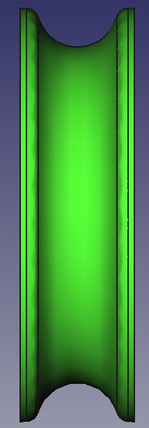
So this is the Gen3 Hy-Con flywheel, the "rotor-centric" that I may have referred cryptically to at some point. The profile geometry is the same as the Gen2 with all its refinements in that regard. The big change happens on the other side of the rims. Up to this point I had been designing flywheels with the structural concept of old-school, shaft-mounted wheels from the DC dark ages. I just replaced the shaft bore with a bolt pattern to hook onto the rotor flange of the outrunner, much like an engine flywheel. So did FDL Jesse and most others. I was pondering optimal print parameters and possible design revisions for these Gen1/Gen2 wheels in light of the cage stiffness observation and some concentricity/balance questions with them as well.
Ultrasonic2's Ultracage wheels came to mind, in which there a small step to use the rotor OD as a pilot diameter/locating feature to center the wheel, when it suddenly clicked: Why does the web need to carry a bending load, anyway? The rotor has a large external cylindrical surface, why not just use that to both locate and support side load from the rim?
So there it is!
Consider it a synthesis of multiple older concepts:
* The flange-mounted Hy-Con/FDL or shaft-mounted old style wheels: we still use the web to axially position the wheel and to transmit torque.
* The Ultracage rotor-OD piloted wheel, for being my actual inspiration for using the OD of the rotor on an outrunner in this way.
* Kelly Industries outrunner Stryfe cage, since the press-fit hubless "tire" flywheels transmit their side load in the exact same way. Only mine don't rely on that fit to either transmit torque, or to maintain axial position.
These are dimensioned on spec to get reliable solid fit without movement of the wheel on the rotor. If you early adopters print these, be aware you WILL need to scrape down any layer-change blips first to get a mostly-round bore, and then sand to snug fit on the rotor OD (tight isn't necessary). Careful of the motor bearings when fitting these, avoid excessive force or you could brinell them. Aligning the bolt holes is fiddly; use your allen key for the flywheel bolts while pressing the wheel on. For now the 3mm pilot bore is still there and still needs drilling/reaming to clean up just like before.
The most profound immediate result from this design was better concentricity and greatly reduced NVH. Using the rim ID and rotor OD as a locational fit helps deal with printing tolerances and warping and such in the web and automatically pulls the rims into concentricity with the rotor when bolted down. These things feel almost machined, and my printer is still not as perfectly square as I want it, even. The rigidity also prevents things from wet-noodling at speed under imbalance forces and worsening any imbalance.
Recommended print parameters (with 0.2mm layer height 0.4mm nozzle) for the Gen3 are random start point, 3 perimeters, 4 bottoms and 3 tops (Less mass is priority over pretty top layers) and 20% hexagonal infill. The Gen1/2 wheels benefit from more solids. These do not, because there isn't any bending load on the web. It will just add pointless mass and make you need to crank your delays up and have longer lock time.
At this point I should address printed wheels and inertia briefly. Those rims look awful thick, but keep the above image in mind; there is structured infill in there, thus the rims are mostly air. The majority of rim mass in a printed wheel is in the perimeters. This is why the Gen2 wheel design was admittedly kind of dumb - all I ended up doing was moving the inside perimeter outward, increasing its circumference (hence quantity of plastic) AND its radius, while only saving a tiny tad of infill volume inside. Gen3 is probably not optimized for inertia because the top layers start getting heavier with such a thick rim as well as the infill, but its structural benefits are undeniable and the Gen3 runs the same delay settings as my old Gen1 wheels, which are acceptable. Further mass reduction may indeed be explored within reliability/durability bounds to pep up startups.
I also happened to get this image that ought to embody part of the answer to the question "why brushless?" that I often get. Of course there are about 6 different factors in why brushless (inverter PMSM) drives kick DC's sorry ass all the way to Alpha Centauri and back, but packaging is one of them:
There is no way I could possibly achieve a flat cage package like the Hy-Con with brushed motors. That's, at minimum, a 380, at about 3 times the length.
Spambots have been submitting a torrent of garbage comments lately, so anonymous comments are now disabled for the time being. If you're a human or other sentient being, please create an account and continue posting feedback and ideas.
So far what I have been testing and playing nerf with is very nearly the original version of the Hy-Con system. There has been, up to this point, only one 9.5mm gap wheel that has existed completely unchanged from the get go, and the "Beta" cage used by the Model Pandora development gun is basically the Protocage repackaged save for one fillet. I guess I did well enough, but make no mistake, this is far from finished.
Problem one is that I have been having incidences of a specific and aggravating malfunction with this cage, which has been occurring solely with used waffle darts (never anything else, especially not accustrikes). The failure mechanism is the foam being dragged around with the lag side of one of the flywheels after the contact zone and getting sucked into the little gap where the bore re-forms, created by the extremely concave wheel and the cylindrical flywheel cavity in the older Hy-Con cages. The thing then seizes up tight as a rock. Sometimes the dart can be unwound out the breech or muzzle by hand. Other times a rod is required. Not a good situation.
I was aware of this misfeature, as well as potential solutions to it, and it was my greatest uncertainty when I designed the original Hy-Con system. The reason for its persistence is or perhaps was that machined cages are or perhaps were planned down the road, and any internal geometry gnarlier than a cylindrical flywheel cavity would probably result in a significant cost increase and prevent a one-piece cage from being possible to assemble.
Unfortunately, this does not appear to be working out.
This blaster must shoot any common super/ultrastock ammunition, and it must be able to shoot garbage. It's allowed to chop or mutilate garbage in any way, and it is also allowed to have garbage accuracy and consistency with garbage as is the reality of garbage, but it is never allowed to stop firing and require attention to clear, even if the ammo is garbage.
And so the CADding begins again. I am holding off on further work on the Production T19's "Gamma" cage for the moment until I get the internal geometry of the Hy-Con cages nailed down and field tested. To that end, this is what I am calling "Beta Prime", a straightforward addition of the experimental feature to the old Model Pandora cage.
Note those protrusions - they stick down into the flywheel grooves, and fill that stupid little offending gap in so stuff hopefully can't get pinched in there and cause a mess. They have about 0.75mm clearance off the rims of a 9.5 wheel, so there is a bit of room left for the 9.0.
This is actually a feature the PFDL cage has had for a while now. It probably is overkill with the low envelopment there, nor does it seem to be necessary with high-envelopment smaller diameter systems like Eclipse, Ultracage and DrSnikkas cages that generally just have a cylindrical cavity and ignore that gap, but I may have discovered a case (high envelopment AND one of the largest diameter systems ever in practical use) where it is very, very necessary to have that little groove filler doohickey.
I should also mention my suspicion that this troubling malfunction is all the fault of waffle darts all along once they get used and the tips start getting loose - the root cause may be the waffle tip grabbing/sticking in the 14mm barrel and causing the foam to buckle or bunch-up behind at which point the lag sides of the wheels are going to nip the foam. I had the same exact jam happen when I was using TBNC David's FDL for one round and put a couple hundred rounds through it. The difference is that when T19 does this, the dart becomes a mangled, compacted, FUBARed shitshow. When the FDL did it, the dart was still pinched and the motors still locked up, but grabbing the dart and ripping it out, then dryfiring dislodged all the debris and restored functionality. That I am guessing is the limit to the value of the gap-filler doohickeys and the true solution is to not shoot those darts and use something else. I am having massive second thoughts on Accustrikes/clones - they are AWESOME in CQB and HvZ.
Anyway, here's the result when you add wheels:
Note the protrusion is asymmetrical. The motor mount side cuts it a bit closer to the wheel profile with a 45 degree edge there in the hopes of printing more easily.
You can also clearly see another related change - the cage no longer splits straight down the bore axis. The parting line was moved 4mm from the motor mount part toward the cover part. That gap filler protrusion makes assembly impossible if it is not entirely in the motor mount section of the cage. Note it also makes assembly impossible if the guards or anything else are integrated into the motor mount section without sufficient clearance and block the sides of the motor mount. You must be able to mount the wheel to the motor, slide the motor in from the side, and bolt it down to get the wheel rim past the protrusion.
There are also some minor external changes on the Beta Prime cage from the previous Beta. Guards were thinned by about half but are still quite robust, and some edges have fillets. No big deal.
I have also modelled a new series of wheels. Changes include more refined rim backside geometry, 0.5mm larger OD to take better advantage of the standard Hy-Con cage clearances and take the rim-to-rim clearance down to a nominal 0.5mm, a series of gap settings that presently range from 11mm to 9mm, and radiused rims rather than chamfered rims, which are a bit smoother and sacrifice less contact at the edges.
This one is a 10mm, incidentally. I have high hopes for 10mm with this system being quite competitive on velocity but easier on darts than the 9.5.
This cage has Gen 1 wheels. Note what happens with those rim chamfers. Also note what is considered a large rim clearance in this day and age, not a fitting thing for the original "100%" envelopment cage.
This one has Gen 2 - note softer edge provided by the fillet instead of the hard chamfer, and note the closer rims and generally much better fidelity of the hydrostatic compression profiles to the ideal circle.
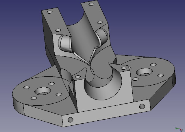
Finally, since I didn't get any images of the real blaster that show the drivetrain guts of a T19, have a Model Pandora cross-section. Perhaps that will clear up some things.
Specifically, look right above the NEMA 17 mounting pattern and you can see the cavity where the crank web sits, and above that, the bolt guide rails. The bolt is completely 2-D like a sheet part (the proto one IS a PVC sheet part like the crank web), and is about 6mm thick. The limit switch bolts to the little perch behind there. The purple top cover forms the upper rails, capturing the bolt in there, and the rest is just a magwell, a closed breech guide and a cage and that's all there is to it.
The stepper motor's shaft is shortened considerably, before anyone asks.
More updates once I get my Prusa going. That's gonna be fun...