Wednesday, April 10, 2019

Project ACS: introduction and prototype.

UPDATE: Developmental Release - Files (STEP and mesh): https://drive.google.com/drive/folders/1I0v7zyEGdxN3NCPVDQfZn_9ZpjCpnTKV?usp=sharing

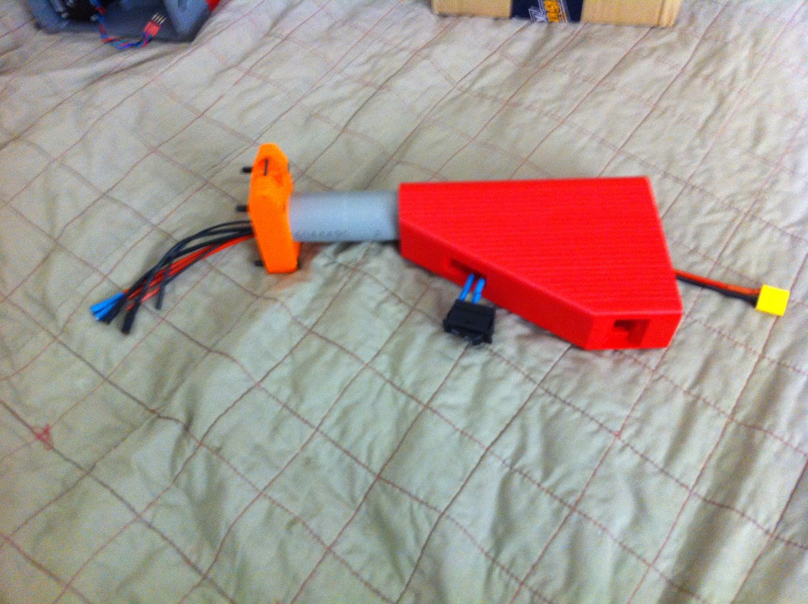
Stryfe for scale. 20 round Vorpalmag loaded.


Etymology: ACS AC-driven compact submachine gun

I always wanted a mag-in-grip SMG of my own ever since native short dart mags became a practical reality with standard formats and the advancement of desktop 3D printing.

Of course, mine would need a certain set of mandatory features and qualities:
  • No DC motors!
  • No gears!
  • No shaft press fits!
  • All drives tolerate blocked/stalled/locked-rotor condition
  • All mechanics tolerate aforementioned
  • Software-controlled with single-trigger operation
  • Closed-loop speed controlled flywheel drive
  • Monolithic construction (i.e. no clamshells)
  • Overall rugged and heavy-duty
So this is my first crack at it and my first "little side project" sort of blaster.


It's more or less a mini T19. It has a bare bones Core-compatible controller and drives the pusher with a hybrid stepper. The drivetrain is a scaled-down T19 drivetrain of 35mm stroke. The flywheel system is a scaled-down Hy-Con derivative which I am calling Mini-Con (not to be confused with the Dixon/Bregg Tiny-Con).


The red wheels are Mini-Con wheels and the teal wheels are full size Hy-Con for scale.

This system is 41mm centerdistance, and uses the DYS/Quanum BE1806 motor (purple motor at the bottom of the image). These initial wheels are 9.5mm "magic number" gap as usual. Shot down the barrel at the cage:


You can also see in the previous image a shockingly short NEMA 17 motor - this is a OSM 17HS08-1004S. Testing this motor was an objective of doing this project in the first place, and said evaluation is still ongoing. My initial impressions from running it in the prototype are that this little motor, even with the very well balanced 35mm stroke drivetrain in this blaster, is not a good choice for a bolt drive. It just doesn't have the guts, even when driven at up to twice the rated continuous phase current. Hybrid steppers are not a modern or high torque density design, as PM synchronous machines go, so it isn't unexpected.

For now, the one existing prototype is running an ordinary, full size 17HS16-2004S1, familiar to users of the T19 and direct drive FDL-2. This performs very solidly, of course. It will reliably cycle at ROF of 16+ rps that no short dart mag yet tested or devised will handle without skipping.

Here, have a cross-section:


This should illustrate the construction and details of the layout. The entire receiver is composed of two parts that run the full length of the unit. The length was chosen as 249mm for reason of the Original Prusa i3 Mk2 and onward having a 250mm X-axis dimension of the build volume. Underneath this is a single-piece lower receiver. On top is a top cover, which forms the electronics compartment.


Flywheel motor controllers, however, are housed in cavities in the "main" and "cover" components beside the barrel in front of the flywheel system.


These controller cavities are sized generously to accommodate i.e. 20FS Afro or ZTW Spider 30, or similar higher-rated, older design non-minaturized units, despite the smaller motors in this application. Accommodating a variety of controllers was easy without an impact on external bulk since the need for placement of controllers somewhere was considered early on.


This is the "main" receiver component. The vast majority of critical geometry for flywheel system, breech and drivetrain went into this one part. You can see the phase wire ducts into the controller cavities. Also note the barrel. The 14mm control bore is kept normally short to save velocity. A fillet is provided at the step in the bore to prevent the printer from generating a corner swell burr on the crown and require manual crowning which would be a PITA down inside the bore of one of these things. This was successful.

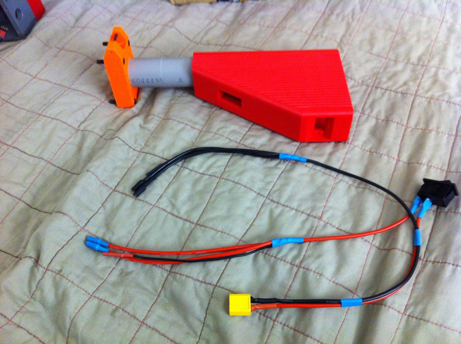
Here's an earlier stage of progress, and this is a good image to point out the mag release design as well as the trigger switch.


The mag release pivots about the lower end of the trigger guard and has ambidextrous thumb tabs that push forward to release. Has a similar feel to realsteel pistol mag releases.


Tension is provided by a compression spring between the release and the back of the trigger, which also provides trigger return force.

You can see in the above images 2 counterbored bolt holes on the side of the receiver in a standard full-size microswitch pattern: these are for the trigger switch, housed in a cavity behind there and just above the slight bulge on the bottom of the lower, oriented vertically. The trigger has an extension which fits into a recessed channel in the top of the lower receiver and reaches back and to the side where the switch plunger is.


Bit of trivia: The lower prints upside down on the bed. The bottom of the trigger guard is bridged. No supports.

Back when I started on this, Katanamags were all the rage and the competing Worker Talon format was relatively untested. Katana format also lends itself to a more comfortable grip design, so I went with it.

I made a comment of this form to MeakerVI on reddit about that decision:

... took my Katanamags in hand and ran straight off a cliff overlooking the Rubicon ...

What this references is that the ACS is rather tightly integrated. Supporting an alternate mag format would not be as simple as blowing a differently-shaped hole in some parts - that might break through or critically reduce wall thicknesses in multiple places owing to the body length of these formats differing with Katana being shorter. I would have move multiple, multiple features around to make it safe and proper, to the point that it may as well be a partial remodel - and if it's a heavy redraw, it makes no sense not to ALSO include many other lessons learned. So for the purposes of ACS-I, Katana is a done deal.


This indeed proved to be a bit of a regret. Or... did it? I don't know, to be honest.

All I do know is that the actual OEM Jet Blasters Katanamags did not survive, I must have smashed them on something on the way downstream...

Seriously, may I rant? Jet Katanamags suck! Follower sticking issues, tolerance issues, flexible flimsy bodies, and that gaping Chauchat-style slot/window down both sides - nope.

This may be the primary advantage of Talon format in the end - the OEM Talons are actually good mags. But when considering community-sourced designs, there isn't anything necessarily, inherently wrong with the Katana format. The distinctions and merits of printable mags tend to be format-independent. So to that end I have been printing Vorpalmags and working on assorted improvements to the Vorpalmag design, to decent success.

But what still stands out to me now that I have a fast full auto, short dart blaster is that even a mag which by all mechanical means ought to be a great feeding unit tends to be much more problematic with short darts and suffer a ton of tip sticks and stack tilting issues which lead to often skippy feeding. Dart foams simply don't resist the stack flexing/tipping as well when they are slightly less than half as long. It's the same elastic modulus of material but less than half the size. So it's squishier. Pretty inherent. This is probably the typical vexation I run into in the hobby which I tend to feel alone in; where numerous other people do or use something apparently without trouble judging by the posts and reactions, and then I try it out, am disappointed, and find that there is an inherent reliability problem in my book and it was all along that I have unusually high standards.


This was my first exploration of 3D printed Picatinny rails. These are sliced with 5 perimeters, 100% rectilinear infill and came out very nice, very sharp quality and robust enough. They feel about like nylon Magpul rails as far as material hardness, though with PETG's notch sensitivity issues at times they are probably not as strong as nylon would be in some impact scenarios. But they should do.


Top cover has a recess for the NEMA 17 bolt motor's endbell to reduce vertical height in the full size NEMA version. This area slices as only 3 layers thick, with 0.2mm clearance to the motor endbell to account for any extrusion texture on the top layer.

With this part being printed with Yoyi clear PETG, this area is quite transparent with barely visible extrusion lines. This might be useful at some point. Like, to environmentally seal something that has a display. I'm gonna have to keep that in mind.


The underbarrel rail is there with the understanding that a foregrip likely be mounted there since this is not a conventional layout and there isn't anything for the support hand to grab without mounting something for the purpose, so a hopefully sufficient number of bolts are used here.


Some factors I am unsatisfied with:
  • The MAC-10 like appearance I went for is inherently bricky and has a clumsy vibe. Perhaps I will work on restyling top covers some other way.
  • The vertical height of this layout is a bit much. It's certainly no worse than a MHP-15, but is still seemingly ungainly.
  • The layout is not the most efficiently packaged in general: for instance, the pancake motor version's top cover height is constrained not by the motor or the Core board, but by the battery which is already fairly minimal and isn't getting any thinner. And the lower effectively wastes 6mm of vertical height with the full-coverage mounting flange onto the upper receiver. The drivetrain placement is also a bit suboptimal for total package height. More could be done to jigger things around, I just have to figure out what way to best do that.
  • Feed system could use some different and/or more modern technology than a hybrid stepper motor to reduce bulk. This would be a good solenoid use case. It might also be a good case for the next-gen direct drive project of mine.
  • The horizontal flywheel system is also annoying. I included this feature in this case because it was part of packaging improvement attempts early on, but the vertical height I was trying to avoid (without micro-format systems I didn't want to saddle the design with) resulted anyway due to the above.
  • I don't like small-format flywheel systems. Actually, I kind of ...detest them intensely. This sounds and feels like a Stryfe-size system because it is, and after so long of using full size Hy-Cons, I hated it when I ran this at the speed it would need to be supercritical (about 34k). I'm running this at 25k and screwing the velocity I could get with more speed because it's so much more professional and easier on the nerves at 25k. (Sadly, for a compact SMG, there's nothing to be done.) But this reinforced the idea that this is a Side Project Sidearm Secondary Thing and that big primaries I design are going to have the biggest systems they can suffer. I'm also going to go significantly bigger (70mm centerdistance is planned) than original Hy-Con very soon as an experiment and T19 option.
ACS-II will be substantially and fundamentally different. It's pretty vaporous how right now, though.


Here's a mockup with a stock that shows where this is headed once I get around to designing and printing the retractable stock for it.

In the end, despite my misgivings about this little detour not being the best a SMG can be, I think I got somewhere with ACS-I. Smaller than a MHP by a LOT, no clamshells, no DC, no plastic gearboxes, no ridiculously fragile parts, and no other jank, really. It's a solid, clockwork little thing when the mags cooperate. Combat test to follow.

Saturday, March 30, 2019

Bulk PVC sheet thermoforming, the easy way


Sheet PVC is a very useful material for fabrication of a variety of nerfy things. It's easy to carve, amenable to solvent welding, easy to thermoform, lightweight, and strong. This makes it ideal for making switch mounting brackets, internal structural pieces, bridging gaps in shells, shims and fit adjustment, rapid prototyping . . . the list goes on. While blaster shell scraps can also be used for these purposes, sheet PVC is often more convenient due to being thicker, more readily available with larger flat areas, and of course much easier to thermoform than ABS.

I've taken to preparing sheet PVC in bulk. It's much more convenient than thermoforming each little piece of pipe as-needed, as flat sheets are usually the shape that I want to start from when making each PVC part.

Here's how.

Thursday, March 28, 2019

Tuesday, January 15, 2019

T19 Build Guide - Part 12 - Final Assembly and Commissioning

Previous: Part 11 - Core Controller Firmware

Tools:
  • Allen wrenches
  • Multimeter/Voltmeter
Parts/Materials:
  • T19 breech/cage/barrel assembly
  • T19 drive section assembly
  • T19 stock assembly
  • T19 grip assembly
  • T19 Core board
  • T19 logic power module
  • T19 DC bus harness
  • Flywheel motor controller x 2
  • Mag release spring: Use any small spring that fits into the drive housing spring perch and has a solid height that allows the mag release to release mags - approx. 4mm diameter x 12mm free length, relatively light, to suit desired release tension
  • White lithium grease
  • 14.8V battery - recommended for T19: Turnigy Graphene 4S 1500mAh 45/90C
  • Full length .50 cal superstock standard magazine for testing
  • Darts, .50 Hassenfeld/"Full Length", soft tip (NO FVJ or Voberry or etc.)
  • AIM Sports 12" x 0.40" aluminum Picatinny rail segment
  • 10-24 x 1/2" and 5/8" length SHCS for rail installation


DRV8825 prep:

Adhere the supplied heatsink, if you received one, to the underside of the DRV8825 board where the gold-colored thermal pad is using its double-sided thermal adhesive tape. Make sure it is centered so that it doesn't hit the socket headers when plugged in.


N.B.: It is common to see these heatsinks attached to the top of the DRV8825 IC package. The DRV8825 is not designed for that to be a thermal path and the package plastic is obviously plastic and high thermal resistance and doesn't really help much to stick that heatsink on there. The thermal path is intended to be the thermal pad on the underside of the IC package (TI "PowerPAD"). The main heatsink is the copper on the PCB, including the bottom thermal pad connected to the topside by all the vias. You can put the heatsink on top if you like, or even not use one of these add-on heatsinks (the main heatsink is the board itself anyway, and if adjusted correctly the driver should not run hot in this app) if you didn't get one with your DRV8825 board.

(N.B. 2: Some installations, such as 3D printers, my own Model Pandora T19 prototype, and the FDL-2 early AC version bolt drive boards, specifically avoid putting the heatsink under the board on the thermal pad and instead put it on top of the IC package because they put the DC link capacitor under the board. Do not do this. There is a reason I don't do this nowadays. This is stupid design - electrolytic capacitors should NOT be thermally near a heat-releasing component, which the driver is, and also, the axial lead capacitors commonly placed under these driver boards are all junk in terms of ESR. An inverter DC bus cap should be as low ESR as possible. Use a radial lead low-Z capacitor and put it away from heat sources.)

Core board installation:

Mount with 4 self-tapping washer head screws (anything that will bite into the board mounting holes and is about 6mm long). I use random screws from scrapped toygrade bits of many years ago


Drive stack assembly:

Drop the spacer on. Plug the bolt limit switch into the Core board. No polarity to this connector.


Lubricate the drivetrain with white lithium grease, particularly: bolt yoke side thrust faces, bolt rail surfaces upper (drive cover) and lower (drive spacer), crank pin and bolt yoke slot, and the bolt tip notch in the spacer and bolt tip (wipe off excess grease here to prevent ammo contamination and possibly poisoning the friction surface on the flywheels).


Failure to lube the drivetrain can result in part galling.

Don't use hugely excessive grease quantity or leave blobs that aren't on contact surfaces, to avoid mess.

Start the 6 upper drive stack bolts and torque evenly.


Drive section to front end mate:

Stand up the drive section on its rear end. Insert the mag release spring into the drive housing spring perch.


Drop the breech/cage assembly over the bolt tip and align it to the drivetrain stack. Test mag release motion and spring non-binding.


Start 2 3/4" length 6-32 SHCS (top) and 2 1/2" length 6-32 SHCS (bottom). Torque evenly.


Test mag release function with a mag.


DC bus harness installation and stock installation:


Insert the ground squid through the switch cutout in the stock. Jockey it down the stock tube and out the stock base hole.


Insert the battery connector through the switch cutout and feed it toward the rear of the stock.


Insert the positive squid and jockey it through the stock tube along with the ground one.


Insert the switch (I/On position toward the front of the blaster) fully into the switch cutout. It should seat flush and clip in place.


Inside the battery box:


Feed the ends of the squids through the wire hole in the rear drive housing bulkhead and bolt the stock on; torque evenly.


(ignore the side covers on for now)

Motor controller installation:


Plug a motor controller into each motor's phase wires.

If you have a motor test setup/servo tester/throttle generator, this is the time to give each a test rev to verify correct phase rotation. If the flywheel spins the wrong direction, exchange the connections of any two phase wires. Otherwise you will need to verify this after plugging in the blaster controller.

Feed the DC bus leads and the throttle cable of each controller through the wiring holes in the breech and drive housing.


Carefully, without pinching any wires, tuck the controller and phase wire connections into the controller compartment and install the controller cover.


Repeat for the other side.

Rail installation:


Bolt the rail on with the two 10-24 SHCSes.


Be mindful of screw length in the front mounting hole. If the screw tightens up prematurely while threading in, stop and verify length and hole depth.

Final wiring connections:

Plug the flywheel motor controller DC bus leads into the squid harnesses.


Plug the flywheel throttle cables into the throttle connectors - be sure to connect the signal pin of the controller to the signal pin of the Core board and the ground to the ground. As I built this backplane, the signal pin is on top when looking into the DH with the muzzle facing left.

Plug the logic power module into the last 2 (20AWG, 2mm bullet) wires from the squid harness, observing polarity;


...and plug the output connector into the Core board. (WARNING: Don't plug in the logic power connector backwards. Refer to how you wired this in Part 7.) Tuck the module into the drive housing.


Grab the grip assembly and plug its cable into the trigger connector on the Core board. It's 50/50 whether you will get the polarity correct - if not, the blaster will not fully boot and complete its selftest routine.


First Light:

VERIFY ALL WIRING CONNECTIONS! This is the one last chance you have to correct any brain fart that could lead to magic smoke!

Plug in a sufficiently current-capable 14.8V battery, such as the recommended 4S 1500mAh 45/90 Turnigy Graphene.

Disconnect the bolt motor from the board (if you got ahead and plugged it in earlier), since we have not adjusted the current control on its driver yet.

Flip the switch. The processor card LED should light up. You should get a SimonK power-on selftest beep train, an arming beep, and then a throttle blip from both motors. Both flywheels should be turning forward.

Troubleshooting at this stage:
  • If you don't get the throttle blip indicating that the Core controller completed selftest and is ready to fire, your trigger connector is backwards, resulting in a constant trigger-down input when the trigger is up. The blaster won't boot if this happens, it will hang indefinitely waiting for trigger release. Shut the power off and reverse it.
  • If a flywheel is turning the wrong way, its phase rotation is incorrect, swap any two phase wires.
Bolt drive current adjustment:

The DRV8825 uses a reference voltage input to set the current regulator setpoints. This voltage is derived from the 5V rail by a trimpot on the carrier board.

Disconnect the stepper motor from the Core board, if you plugged it in earlier. Power up the blaster. Measure the voltage between a ground pin on the DRV8825 carrier card and pins 12 and/or 13 of the DRV8825 IC package (which should be electrically connected; or use the exposed via near this area ONLY if using a Pololu brand board with a Pololu logo on it and NOT a Chinese generic board).

Source: RepRap Wiki
FOR GENERIC (non-Pololu) 8825 BOARDS: Do NOT measure that exposed via! Measure the IC pins 12 and 13 by seating the probe between both, which are connected. This confusing via looks like the one provided for a meter probe tip on the Pololu board, but is NOT connected to Vref on this version of the PCB.
Shut the power off before adjusting! The DRV8825 often shuts itself down if the pot is turned while powered up. Power down, adjust, power up, and measure.

DANGER: There is a ground pin immediately next to a DC bus pin (the last one on the end) on the DRV8825 carrier. DO NOT SHORT THESE TO EACH OTHER WITH THE PROBE TIP while measuring or else there will be fireworks!

For this application and motor, set Vref to about 1.0V (about 2.0A phase current).

See also https://reprap.org/wiki/A4988_vs_DRV8825_Chinese_Stepper_Driver_Boards#Trimpot_adjustment

Plug the bolt motor back in. (Rotation direction doesn't matter.)

First Cycles:

Power up again, now with the bolt drive ready to run. You should now get a growl from the bolt motor before the flywheel blip when booting up. If the bolt was not at home position when assembled, it should find home automatically on startup.

Ready for the moment of truth? Pull the trigger!
  • Both flywheel drives should spin up smoothly and simultaneously and snap hard up to governed speed.
  • The bolt should cycle and return home.
If you didn't use a throttle generator to manually "exercise" the flywheel drives and verify proper startups earlier, do this now by firing. Do lots of 0 rpm cold shots. Also, wait until the motors spin down to very low speed and then fire while still turning - this is a common case for a defective controller to exhibit symptoms. NO misfires, delayed starts, or anything except smooth, simultaneous spinups should happen no matter what situations you try to fire under.

Power down, then hold the trigger down and power back up. Once SimonK says hello, release the trigger. You should get two bolt motor growls before the flywheel selftest rev, indicating turbo mode (actually alternate preset mode, configured as a turbo mode in stock Core) is active. Dryfire now - you should have 13.8rps ROF with stock Core, and the bolt drive should run smoothly at this speed.

Stick a loaded mag in and fire your first darts.

Once satisfied that the mechatronics operate properly, bolt the grip base on (being careful not to pinch any wiring), and you are 100% done.


Welcome to the brotherhood! Give your brand new blaster a good shakedown shoot before hitting the field. This is also a good time to familiarize yourself with the T19's handling.

(Battery installation note with the 4 cell Graphene: Insert it into the stock wiring end first and horizontal with the wiring exiting toward the top. It should sit at about a 45* angle with the rear end clear of the stock buttplate and should not push the switch wiring out of place, and should not need any foam to not rattle.)


Righty allmighty, keep things square, and go teach some fools what a T19 is!

Next: Part 12 - Tuning and Customization (coming later)