Tuesday, January 15, 2019

T19 Build Guide - Part 12 - Final Assembly and Commissioning

Previous: Part 11 - Core Controller Firmware

Tools:
  • Allen wrenches
  • Multimeter/Voltmeter
Parts/Materials:
  • T19 breech/cage/barrel assembly
  • T19 drive section assembly
  • T19 stock assembly
  • T19 grip assembly
  • T19 Core board
  • T19 logic power module
  • T19 DC bus harness
  • Flywheel motor controller x 2
  • Mag release spring: Use any small spring that fits into the drive housing spring perch and has a solid height that allows the mag release to release mags - approx. 4mm diameter x 12mm free length, relatively light, to suit desired release tension
  • White lithium grease
  • 14.8V battery - recommended for T19: Turnigy Graphene 4S 1500mAh 45/90C
  • Full length .50 cal superstock standard magazine for testing
  • Darts, .50 Hassenfeld/"Full Length", soft tip (NO FVJ or Voberry or etc.)
  • AIM Sports 12" x 0.40" aluminum Picatinny rail segment
  • 10-24 x 1/2" and 5/8" length SHCS for rail installation


DRV8825 prep:

Adhere the supplied heatsink, if you received one, to the underside of the DRV8825 board where the gold-colored thermal pad is using its double-sided thermal adhesive tape. Make sure it is centered so that it doesn't hit the socket headers when plugged in.


N.B.: It is common to see these heatsinks attached to the top of the DRV8825 IC package. The DRV8825 is not designed for that to be a thermal path and the package plastic is obviously plastic and high thermal resistance and doesn't really help much to stick that heatsink on there. The thermal path is intended to be the thermal pad on the underside of the IC package (TI "PowerPAD"). The main heatsink is the copper on the PCB, including the bottom thermal pad connected to the topside by all the vias. You can put the heatsink on top if you like, or even not use one of these add-on heatsinks (the main heatsink is the board itself anyway, and if adjusted correctly the driver should not run hot in this app) if you didn't get one with your DRV8825 board.

(N.B. 2: Some installations, such as 3D printers, my own Model Pandora T19 prototype, and the FDL-2 early AC version bolt drive boards, specifically avoid putting the heatsink under the board on the thermal pad and instead put it on top of the IC package because they put the DC link capacitor under the board. Do not do this. There is a reason I don't do this nowadays. This is stupid design - electrolytic capacitors should NOT be thermally near a heat-releasing component, which the driver is, and also, the axial lead capacitors commonly placed under these driver boards are all junk in terms of ESR. An inverter DC bus cap should be as low ESR as possible. Use a radial lead low-Z capacitor and put it away from heat sources.)

Core board installation:

Mount with 4 self-tapping washer head screws (anything that will bite into the board mounting holes and is about 6mm long). I use random screws from scrapped toygrade bits of many years ago


Drive stack assembly:

Drop the spacer on. Plug the bolt limit switch into the Core board. No polarity to this connector.


Lubricate the drivetrain with white lithium grease, particularly: bolt yoke side thrust faces, bolt rail surfaces upper (drive cover) and lower (drive spacer), crank pin and bolt yoke slot, and the bolt tip notch in the spacer and bolt tip (wipe off excess grease here to prevent ammo contamination and possibly poisoning the friction surface on the flywheels).


Failure to lube the drivetrain can result in part galling.

Don't use hugely excessive grease quantity or leave blobs that aren't on contact surfaces, to avoid mess.

Start the 6 upper drive stack bolts and torque evenly.


Drive section to front end mate:

Stand up the drive section on its rear end. Insert the mag release spring into the drive housing spring perch.


Drop the breech/cage assembly over the bolt tip and align it to the drivetrain stack. Test mag release motion and spring non-binding.


Start 2 3/4" length 6-32 SHCS (top) and 2 1/2" length 6-32 SHCS (bottom). Torque evenly.


Test mag release function with a mag.


DC bus harness installation and stock installation:


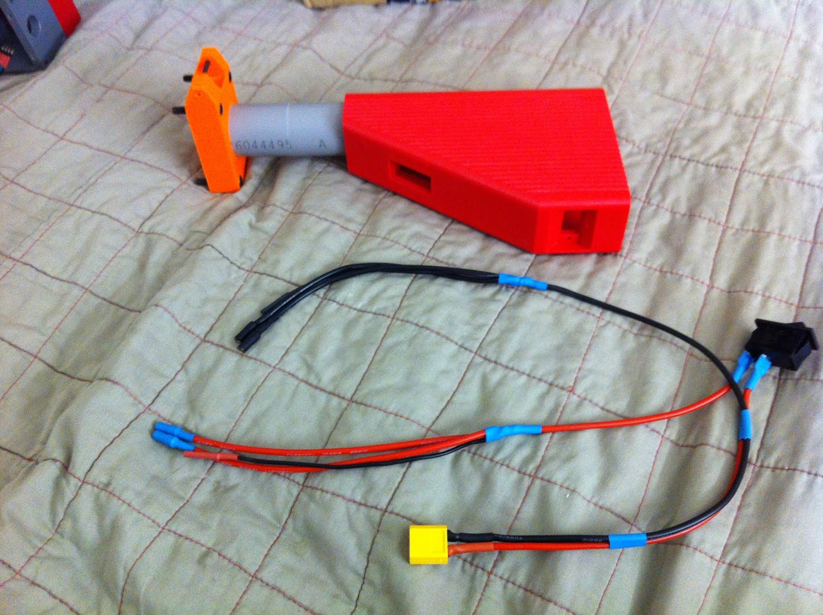
Insert the ground squid through the switch cutout in the stock. Jockey it down the stock tube and out the stock base hole.


Insert the battery connector through the switch cutout and feed it toward the rear of the stock.


Insert the positive squid and jockey it through the stock tube along with the ground one.


Insert the switch (I/On position toward the front of the blaster) fully into the switch cutout. It should seat flush and clip in place.


Inside the battery box:


Feed the ends of the squids through the wire hole in the rear drive housing bulkhead and bolt the stock on; torque evenly.


(ignore the side covers on for now)

Motor controller installation:


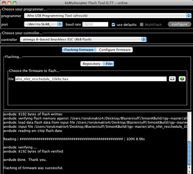
Plug a motor controller into each motor's phase wires.

If you have a motor test setup/servo tester/throttle generator, this is the time to give each a test rev to verify correct phase rotation. If the flywheel spins the wrong direction, exchange the connections of any two phase wires. Otherwise you will need to verify this after plugging in the blaster controller.

Feed the DC bus leads and the throttle cable of each controller through the wiring holes in the breech and drive housing.


Carefully, without pinching any wires, tuck the controller and phase wire connections into the controller compartment and install the controller cover.


Repeat for the other side.

Rail installation:


Bolt the rail on with the two 10-24 SHCSes.


Be mindful of screw length in the front mounting hole. If the screw tightens up prematurely while threading in, stop and verify length and hole depth.

Final wiring connections:

Plug the flywheel motor controller DC bus leads into the squid harnesses.


Plug the flywheel throttle cables into the throttle connectors - be sure to connect the signal pin of the controller to the signal pin of the Core board and the ground to the ground. As I built this backplane, the signal pin is on top when looking into the DH with the muzzle facing left.

Plug the logic power module into the last 2 (20AWG, 2mm bullet) wires from the squid harness, observing polarity;


...and plug the output connector into the Core board. (WARNING: Don't plug in the logic power connector backwards. Refer to how you wired this in Part 7.) Tuck the module into the drive housing.


Grab the grip assembly and plug its cable into the trigger connector on the Core board. It's 50/50 whether you will get the polarity correct - if not, the blaster will not fully boot and complete its selftest routine.


First Light:

VERIFY ALL WIRING CONNECTIONS! This is the one last chance you have to correct any brain fart that could lead to magic smoke!

Plug in a sufficiently current-capable 14.8V battery, such as the recommended 4S 1500mAh 45/90 Turnigy Graphene.

Disconnect the bolt motor from the board (if you got ahead and plugged it in earlier), since we have not adjusted the current control on its driver yet.

Flip the switch. The processor card LED should light up. You should get a SimonK power-on selftest beep train, an arming beep, and then a throttle blip from both motors. Both flywheels should be turning forward.

Troubleshooting at this stage:
  • If you don't get the throttle blip indicating that the Core controller completed selftest and is ready to fire, your trigger connector is backwards, resulting in a constant trigger-down input when the trigger is up. The blaster won't boot if this happens, it will hang indefinitely waiting for trigger release. Shut the power off and reverse it.
  • If a flywheel is turning the wrong way, its phase rotation is incorrect, swap any two phase wires.
Bolt drive current adjustment:

The DRV8825 uses a reference voltage input to set the current regulator setpoints. This voltage is derived from the 5V rail by a trimpot on the carrier board.

Disconnect the stepper motor from the Core board, if you plugged it in earlier. Power up the blaster. Measure the voltage between a ground pin on the DRV8825 carrier card and pins 12 and/or 13 of the DRV8825 IC package (which should be electrically connected; or use the exposed via near this area ONLY if using a Pololu brand board with a Pololu logo on it and NOT a Chinese generic board).

Source: RepRap Wiki
FOR GENERIC (non-Pololu) 8825 BOARDS: Do NOT measure that exposed via! Measure the IC pins 12 and 13 by seating the probe between both, which are connected. This confusing via looks like the one provided for a meter probe tip on the Pololu board, but is NOT connected to Vref on this version of the PCB.
Shut the power off before adjusting! The DRV8825 often shuts itself down if the pot is turned while powered up. Power down, adjust, power up, and measure.

DANGER: There is a ground pin immediately next to a DC bus pin (the last one on the end) on the DRV8825 carrier. DO NOT SHORT THESE TO EACH OTHER WITH THE PROBE TIP while measuring or else there will be fireworks!

For this application and motor, set Vref to about 1.0V (about 2.0A phase current).

See also https://reprap.org/wiki/A4988_vs_DRV8825_Chinese_Stepper_Driver_Boards#Trimpot_adjustment

Plug the bolt motor back in. (Rotation direction doesn't matter.)

First Cycles:

Power up again, now with the bolt drive ready to run. You should now get a growl from the bolt motor before the flywheel blip when booting up. If the bolt was not at home position when assembled, it should find home automatically on startup.

Ready for the moment of truth? Pull the trigger!
  • Both flywheel drives should spin up smoothly and simultaneously and snap hard up to governed speed.
  • The bolt should cycle and return home.
If you didn't use a throttle generator to manually "exercise" the flywheel drives and verify proper startups earlier, do this now by firing. Do lots of 0 rpm cold shots. Also, wait until the motors spin down to very low speed and then fire while still turning - this is a common case for a defective controller to exhibit symptoms. NO misfires, delayed starts, or anything except smooth, simultaneous spinups should happen no matter what situations you try to fire under.

Power down, then hold the trigger down and power back up. Once SimonK says hello, release the trigger. You should get two bolt motor growls before the flywheel selftest rev, indicating turbo mode (actually alternate preset mode, configured as a turbo mode in stock Core) is active. Dryfire now - you should have 13.8rps ROF with stock Core, and the bolt drive should run smoothly at this speed.

Stick a loaded mag in and fire your first darts.

Once satisfied that the mechatronics operate properly, bolt the grip base on (being careful not to pinch any wiring), and you are 100% done.


Welcome to the brotherhood! Give your brand new blaster a good shakedown shoot before hitting the field. This is also a good time to familiarize yourself with the T19's handling.

(Battery installation note with the 4 cell Graphene: Insert it into the stock wiring end first and horizontal with the wiring exiting toward the top. It should sit at about a 45* angle with the rear end clear of the stock buttplate and should not push the switch wiring out of place, and should not need any foam to not rattle.)


Righty allmighty, keep things square, and go teach some fools what a T19 is!

Next: Part 12 - Tuning and Customization (coming later)

T19 NOT the build guide - Part 10a - Flywheel drive detour

The abstracted requirements for T19 flywheel motor drives
  • 3-phase PMSM controller
  • Sensorless control (no encoders, resolvers, Hall sensors or the like exist for rotor angle feedback)
  • Must support minimum 180,000 electrical RPM (3000Hz) - for this relatively slow application. Make that about 300,000 if we are to extend that to generalized nerf flywheel drive applications.
  • Must have a closed-loop speed control mode (The Hy-Con flywheel system does not have acceptable dynamics with voltage command or "BLDC mode". There is too much inertia.)
  • Inverter rated for: ~24V DC bus, ~20A continuous phase current, ~70A transient phase current (roughly)
  • Must have an agile startup methodology from 0 rpm and undriven state - say, <10ms from receiving a speed command step to development of motor torque
  • Must support 400Hz "RC standard" 1000-2000us PWM throttle signal input for stock blaster controller (though the controller/firmware can be adapted to any protocol)
  • Must be capable of protecting the stator winding and its own power stage from excessive current during sudden shock/stoppage, prolonged locked-rotor condition, or sync loss (sensorless failure)
  • Must be capable of reliably tracking and establishing control of turning, undriven motors
  • Must demonstrate proper operation with the Turnigy Multistar V-Spec 2205 2350kv, or similar 12 slot, 14 pole motors with fractional slot concentrated winding
  • Must be capable of applying zero torque/current to a turning motor (coasting): i.e., not some problematic types of "hobbytroller" (those that run BLHeli flavors, mostly) that always do complementary PWM and yet only do open-loop voltage command, or those that misbehave other ways (BLHeli_32, failure to restart from running) when damping modes are disabled.
  • Must be tunable enough to debug motor performance issues, for example timing for scalar control or FOC parameters for vector control, current control/voltage schedule, ...
  • Reasonably packaged and priced: about like a 20-30A rated hobbytroller.


Any controller that you can lay hands on which satisfies the above, and most critically satisfies them all at once, should do, if you wish to venture outside the sorts of hardware I use. I welcome anyone claiming to find or make this magic drive. Believe me, I have dug through lots of knowledge, datasheets and specs on existing gear so far and everything existing fails at least one way. Ideally it would be 32-bit, have a codebase written mostly in C, do sinusoidal FOC, and have proper current sensors.

T19 Build Guide - Part 11 - Core Controller Firmware

Previous: Part 10 - Flywheel Motor Controllers

Tools:
  • Sparkfun FTDI-Basic Breakout Board, 5V version (or equivalent logic level serial interface) for flashing Arduino Pro Mini
  • Mini-USB to USB-A cable for above
  • Computer with:
    • Arduino IDE
    • FTDI Driver or other serial interface driver necessary
Parts/Materials:
Fire up Arduino IDE. Open Core-26.11.ino:


Select "Arduino Pro or Pro Mini (5V, 16MHz) w/ATmega328" from the Tools/Board menu, if not already selected.

Plug the FTDI board into the APM flash header:


Plug that into the USB port on the machine, which powers it up:


Select the corresponding device file from the Tools/Serial Port menu. If unsure what filename your driver will spawn for the board or any other issues with Arduino IDE or flashing, consult driver documentation or any of the HUGE online resources for Arduino. You aren't the first to flash a Pro Mini!

Click the Upload button to compile and flash. The FTDI board should light up. When successful, disconnect, and insert the APM back into the backplane board.

Next: Part 12 - Final Assembly and Commissioning

T19 Build Guide - Part 10 - Flywheel Motor Controllers


This post is a lot of discussion and info and then we get into work at the end. It will cover the standard option: Atmel ATmega8-based hobbytrollers/RC ESCs, running the modified SimonK variant that I maintain for this specific application. (See the part 10a detour post if you wish)

Here's what to look for in a prospective SimonK Hy-Con (or other flywheel drive) controller:
  • Has an ATmega8 chip... obviously. (Not Silabs C8051F3xx or EFM8BBxxxx, which is the other white meat of 8 bit hobby controllers)
  • Has a large enough inverter: Generally, a suitable board is rated for AT LEAST 20A. Most I would call suitable have a 30A rating on the nameplate.
    • Look at the datasheets for the MOSFETs - they should be rated for at least 30Adc and 120-600+ A transient (depending on the manufacturer's transient rating convention). The Afro RaceSpecMini 20A is an example of a board that has a "20A" rating and yet has SON package devices that are perhaps not up to this app.
  • Is reasonably reputable. Be careful buying unrefined Chinesium, such as "eBay special red SimonK ESCs". You never know what you actually get with those.
  • Is a reasonably modern design so you get modern robust MOSFETs. Atmel-based hobbytrollers go back YEARS and there are some real dinos out there. If you encounter an inverter with P-channel switches in it, that's why. Those would probably do OK, but yeesh, P-channels.
  • Is supported by SimonK
  • Is capable of being clocked at (standard) 16MHz on SimonK, not 8MHz - look up your board type.
  • Is a good hardware design. Some types of boards have layout or parasitics problems with the BEMF sense circuits and are known as frequent sensorless misbehavers/bad starter-uppers. Don't use those here. Google your ESC model.
Two examples of suitable T19 motor controllers. Left: ZTW Spider 30. Right: Afro "20A fullsize".

Some common examples:
  • Afro - 30A full size, 20A full size (which I commonly use), 20A Slim, 30A RSM, and 20A HV versions all have good robust inverters with Fairchild FDMS8018 or Toshiba TPCA8087 devices.
    • The 20 RSM, 12A/12 Ultralite, are not suitable for 'cons and other larger/higher power drives
    • Availability problems. Many of these boards are out of production and stock depleted.
    • Some runs of these have defective ATmega8 chips with bad comparators causing misbehaviors. I run into several 20A fullsizes that act wonky, especially by failing rolling restarts from low speed, and can't to date be compensated for in software.
    • These are afro_nfet and afro_hv (20A HV with dedicated gate drivers) board targets.
  • ZTW Spider - the 30A version is probably most applicable. I have a number of these. Some may not have a one-wire flash bootloader stock like Afroes, and thus need to be unwrapped and ISP-ed with an arduino or USBasp or the like the first time you flash them.
    • These are generally bs_nfet board targets ("Turnigy BlueSeries"), but some differ. Google yours.
    • Watch out for "Spider PRO". These are Slimelabs-powered, BLHeli-running imitators that look similar!
  • DYS SN30 - and SN30A, also SN20/SN20A (use the 30 versions on Hy-Cons), and clones thereof - these are a small, slim, "BLHeli-Era style" board layout. They can be flaky physical quality.
These are just the highest profile ones. Many, MANY hobby ESCs past and present have ATmega8 chips, are SimonK-supported, and are suitable. As the trendy drone market has decided Atmel AVR = uncool lately, it may be necessary to NOT expect to use drone-market controllers that come/came stock with SimonK.

In any case: When dealing with any brand of hobbytrollers, always buy more than the two you expect to use. Same goes for hobby-market motors, really - there are lemons. Waiting for a replacement of the offending drive component when you have a build 99% finished and then find you have a dud part, sucks. You will wind up using the extra later on or else keep as spare if you don't need it.

Tools/Parts/Materials:
  • Computer, with necessary Atmel AVR flashing toolchain. This, at minimum, is avrdude and the device driver/kernel module for whatever sort of serial interface/ISP device/USB dongle you use to connect to the microcontroller or board, but a convenient GUI utility for flashing AVR powered ESCs is KKMulticopter Flash Tool.
  • AVR flashing hardware. If your ESCs have a one-wire bootloader like the SimonK one already installed (which allows flashing over the throttle cable), this can be something like the Afro or Turnigy USB Linker. If not, you need an AVR ISP device and to connect to the 6 ISP pads on the board.
  • If you need to change wiring (The boards should have ~4" DC bus leads with 3.5mm male bullets, a ~10" throttle cable with a 3 pin female 0.1" connector, and ~2" phase leads with matching bullet connectors for your motors):
    • Soldering iron
    • Flux
    • Leadfree solder
    • Wire cutting/stripping tools
    • Heatshrink
    • Connectors
  • The boards, of course.
Here is a 20FS Afro from earlier wired with 2mm bullets to match my motors' phase connectors. I leave these stock bullets on the motors. You can substitute a single-piece three-phase connector, direct solder the phase wires onto the board drone-racer style, or use the existing 3.5mm bullets on these Afroes and change the motor wiring instead - Doesn't matter, just make it hook up and work.


Obtaining the firmware:

I put up tested binary builds as well as the source on on the DZI Google Drive here: https://drive.google.com/drive/folders/1frGGqdCYReqgqNWM6G-BrLLElJN7hRM7?usp=sharing

The current flavor of the fixed-speed wheel drive firmware has all earlier optimizations posted on this blog, plus uses 10kHz PWM frequency with a modification to do 5kHz in startup mode, and is my most robust and tolerant build yet.

If you are using a board I don't publish a binary for or need/want to change governed speed (currently only Afro and 25.5kRPM), or need to fix tuning issues:
  • DIY: Install AVRA (AVR Assembler), and build SimonK from source using my tgy.asm version dropped into SimonK 2015-09-30 - for example, "make bs_nfet.hex" in the directory containing the SimonK source tree. Check the corresponding include file such as bs_nfet.inc first to be sure important settings like timing aren't clobbered by its stock state.
  • In over your head, dislike it, want a life jacket? Message me on Reddit (/u/torukmakto4) or send me an email at torukmakto4@gmail.com with something about SimonK, brushless, Hy-Con, etc. in the subject. Don't use Facebrick PMs or blog comments if urgent (I might NOT receive them quickly), provide as MUCH INFO as possible on your board type, desired governor setting, etc. and I will configure and build a firmware for your application and drop the binary in the Drive.
Here's flashing these Afroes with KKMulticopter Flash Tool:


To properly enter the SimonK bootloader for flashing with a throttle-wire toolstick like this:
  • Connect the programmer to the ESC
  • Then power up the programmer and/or connect it to the computer
  • Then apply DC bus power to the ESC. (If you power it up without the programmer signal, it will boot normally, which is not desired)


Select your programmer type: here an Afro USB linker.

Select the device filename for the programmer. KKMFT should try to autoselect the right device. Doesn't seem to show up? Make sure the driver is installed and works, for instance the Afro USB linker is a Silabs USB serial interface IC and has a driver from its vendor Silabs.

Select "atmega 8-based brushless ESC (8kB flash)"

Select the File tab and click the floppy disk button to pop up the file picker. Find the firmware binary and select it. Note I am using the latest tune of the stock T19 wheel drive firmware (afro_nfet_reschedule_10khz.hex)  for this example. Be EXTREMELY SURE one last time that you have the correct board target built for your ESC!! The wrong build for the board can immediately blow shit up.

Click the green button and have a tense moment while flashing.

When you get "Flashing of firmware was successful", you are out of the woods - at least until you unplug the programmer and it boots for the first time. No smoke? Now REALLY out of the woods.

If you have a test throttle generator, hook up the controller along with a 4S battery and give your still-unproven ESC a test spin with one flywheel of the cage. The drive should spin up smoothly from 0 rpm without any "misfires" and snap hard up to full speed. Restarts from running should be flawless. Restarts from very low but nonzero speed should also immediately start accelerating again. If you do not have one, these tests can be performed later on during commissioning with your actual blaster controller by firing the blaster.

If you have a startup or rolling-start anomaly with this firmware, you probably definitively have a lemon board - try another. Get it squared away. An occasional desyncy, laggy spinup due to a bad chip/board is a failure for this app and needs addressing.

Sunday, January 13, 2019

T19 Build Guide - Part 9 - DC Bus Harness

Previous: Part 8 - Logic Power Supply Module

This is another fairly quick one that will wrap up all the wiring/soldering (unless you have to put or change wires or connectors on a motor controller in the next step).

Tools:

  • Soldering iron
  • Knife
  • Dikes or flushcuts
  • Heat gun or heat source for shrinking tubing
Parts/Materials:
  • 2 x femals 2mm bullet connector
  • 4 x female 3.5mm bullet connector
  • Battery connector to suit your packs, fleet, personal preference, etc. (shown, XT60 male)
  • Bulgin C1300AA rocker switch, high inrush rated (Digikey part 1091-1013-ND) (N.b. This model switch is required by the OE stock with integral switch cutout.)
  • Following silicone insulated fine strand (hi-flex, 200*C rated hobbywire) lengths:
    • 14AWG or 16AWG, black (or other "ground" color), 19"
    • 14AWG or 16AWG, red (or other "positive" color), 12"
    • 14AWG or 16AWG, red, 8"
    • 14AWG or 16AWG, black, 7"
    • 14AWG or 16AWG, red, 7"
    • 20AWG, red, 6" (shown as black, I had no red on hand)
    • 20AWG, black, 6"
    • N.b. Wire lengths for this prebuild are for the OEM stock. Switch setup and battery wiring will change with non-original stocks/alternate battery locations.
  • Heatshrink (1/8", 1/4", 3/8")
  • Leadfree solder
  • Flux 


Note on wire gauge: I would say 16AWG does it. 14AWG is overkill and 14 silicone is a clunky diameter with the thick insulation. I used 16 on this build.

Start off with the switch. Strip, tin, solder and heatshrink 8" red on center pin, 12" red on end pin.


Lay the 7" wire segments along the end of the 12" red (assembled with switch) and 19" black. Mark on the 12 and the 19 the position of the end of these wires and 1/2"-5/8" back toward the end for stripping.


Strip the ends of the 7" red and black and both 20AWG pieces. Do not twist or tin.


Carefully, without nicking the conductor, strip the marked spots on the 12 and 19. Careful blade use accomplishes this.


Twist on the corresponding color 7" piece and 20AWG, all wires pointed toward the end measured from earlier as shown. Apply flux. Solder these splices.


This forms the "squid" harnesses to feed both flywheel drives as well as the logic power module from the last post. The branches will split around the bolt motor inside the drive housing and go toward each controller compartment.

Be sure no solder points/spikes have formed when removing iron, clip off if present to avoid risk of punctured insulation and short in the future as these two high-current splices will coexist nearby. Heatshrink the splices. 3/8" tubing will likely be required.


Terminate squids: 16AWG leads with female 3.5mm bullets. 20AWG with female 2mm bullets.


Add some 3/8" heatshrink bits over the free end of both the 19" black (ground cable) and the 8" red from the switch (positive cable) to strap these battery leads together later. Slide those down temporarily near the switch to protect while soldering battery connector. Add two 1/4" heatshrink pieces to each wire and slide safely away. Terminate with battery connector. Position and shrink all those heatshrink tubes.

This is what the finished DC bus harness should look like.