I have had some requests for improved and more complete circuit diagrams as of late. In this post I will cover some of the basic electromechanical Rapidstrike circuits and their applications, behaviors and issues, as well as some general Rapidstrike teching advice.
To begin with, we have the basic old school American Rapidstrike wiring as in my Standard Rapidstrike guide:

You will note I showed ground connections as per convention rather than snaking a bunch of wires all the way back to the battery and making a lot of clutter.
There is a LOT more to this post after the jump which is why I am breaking it here or at all.
Here it is with some labeling:

Switches are all shown at rest as in an assembled gun. The cycle control (limit) switch is shown held in the operated position.
You will also note that certain conductors have become colored. These are to denote two connections of interest. The red one is where you would insert diode(s) for ROF control. The green one is what makes the difference between the old "live center" cycle control strategy and the newer "dead center".
Live vs. Dead Center Circuits
The original Rapidstrike control strategy is what we can now call the live center circuit.Note something about the trigger switch. The pusher motor's positive lead is connected to its common and it alternately connects that lead between battery positive and the common of the cycle control switch. Really, what we have here is a form of "chain of command" logic. The trigger has priority - and it can tell the pusher to run at any time - but when it is not pulled, it passes authority to the cycle control switch. Whenever you are not pulling the trigger, the cycle control switch is in full control of the pusher. This is a constant in all cycle-controlled Rapidstrike circuits.
In the live center circuit, the cycle control switch's common terminal is connected to battery positive whenever the bolt is not fully retracted, and thus not depressing the switch follower. When the bolt does retract fully and depress the switch follower, that terminal is connected to ground, thus shorting the pusher motor to effect braking.
The advantages of the live center circuit include:
- Sure, predictable trigger response. The trigger-down time required to latch the pusher into completing a full cycle under full motor power at full speed is very short. Semi-auto fire is virtually impossible to "short-stroke" and always has the same lock time.
- Reliable bolt position control. There is no normal condition that will cause the bolt to fail to retract.
- Damage hazard in case of pusher crash. If the bolt encounters an immovable object for any reason (including a magazine collision, a FOD incident, or a severe jam), the cycle control switch will continue supplying power to the motor, which is now stalled and drawing locked-rotor current while applying maximum torque to the gearbox. Unless there is an atypical safety switch or power disconnect handy or an atypical overcurrent protective device is included in the circuit, there is no way to quickly interrupt this condition and it is likely to result in gearbox damage, motor burnout and/or wiring or battery damage from prolonged overcurrent.
- Control stability difficulties. The live center circuit powers the pusher motor until the moment of switch trip during the retraction stroke of the bolt. Thus, the speed of the bolt is always as high as possible for a given ROF setting when the bolt arrives at this point. The bolt then has a very short window of gearbox rotation angle (corresponding to the end of the retraction stroke through the start of the extension stroke) to completely stop. At the end of this window, the switch will cut back to powered operation. If the bolt should overshoot the braking window, the pusher will latch to the next cycle. This can cause troubling runaway conditions if the system is not set up or tuned correctly with absolute attention to detail and boundaries of stability with various component combinations; or if a component fails or degrades in certain ways (such as anything that would cause braking loop resistance to increase). It also poses the risk of a potentially damaging power-brake-power-brake thrash condition that can quickly overheat the motor windings if not stopped promptly.
- Following on from control stability, there is no support at all for operating at ROF settings higher than are fully stable with the given combination of motor, battery and control follower timing specs. This is a double-edged sword, as it does help to enforce the use of controllable settings and avoid wasted ammunition and complaints of uncontrollability. It either operates properly, or it runs away and is unusable until you fix it to operate properly.
- Safety. An unattended, powered gun has a spring-loaded switch held down and ready to begin supplying power at any time. Should there be any kind of mechanical failure of the switch hardware, the pusher could spontaneously start and operate continuously, and could result in a fire hazard, motor damage, or battery damage.
The next development we have is the dead center circuit.

The change here is very simple: Cut that green wire. Seriously, that is all there is to it. Disconnect the battery positive from the cycle control switch.
Looking at the dead center circuit from an authority model again, the trigger switch still "outranks" the cycle control and can always make the pusher go at any time, but when the trigger isn't pulled, the cycle control switch only has authority to brake the motor - not power it. The only way the pusher motor gets power is for the trigger to be pulled.
This strikes down every major flaw of the live center circuit in one fell swoop. Advantages:
- Releasing the trigger will cut the power to a crashed pusher.
- A runaway is physically impossible. A bolt overshoot that exceeds the braking window and trips the cycle control switch coasts harmlessly to a stop, since the switch does not have the authority to apply power.
- A "long-stroked" (think, inverse of short-stroking) trigger pull that overlaps part of a braking window will not cause a single trailing overshoot and run-on shot as with live center. Those who shoot live center guns will know what I mean. It is very distinctive.
- Stability is inherent. Bolt position control will be worsened by exceeding "live-center stability limits" for ROF and other parameters, but the system fails in a very benign manner. It allows running a much wider range of ROF options, and is tolerant of improper tuning and component selection, and failure. It is not critical that the cycle control switch and follower be set up properly, the motor have adequate braking torque, or the ROF be matched to other parameters, or even that the cycle control hardware work at all - it will still shoot quite happily!
- High safety. Like the flywheels, the only current path between the battery and the pusher motor is now a single normally-open contact which is sitting at rest with no forces acting on the switch body, and any bolt movement cannot trigger motor startup.
- Indefinite trigger response. A "short-stroke" may not fire a shot, since the first few mm of bolt travel do not latch the pusher motor on. An "almost-short-stroke" may fire a shot, but with a longer lock time than usual as the pusher gearbox coasts during part of the cycle. Exacerbating these issues is...
- Worse bolt position control. The bolt may not end up open every time, and may cause a jam in certain rare cases during reloading. In addition, the unpredictable starting bolt position tends to vary the lock time considerably on top of the inconsistency of pusher operation without guaranteed power during a guaranteed portion of the cycle.
Recommendations
Live center for- Players who shoot a lot of semi-auto.
- Players who need reliable response and consistent lock time on every shot.
- Less than 10-11 rps ROF and proven build specs; or experienced tech-savvy builders.
- Maximum reliability and performance in individual firefights.
- High-speed builds - greater than ~12.5 rps ROF.
- Players who primarily shoot full auto in every engagement.
- Maximum equipment reliability overall, possibly at the expense of control.
- Getting around the need for finicky tuning to shoot fast.
- Making subpar parts work to shoot fast.
The Two Switch Circuit
This is a non-cycle controlled circuit. The pusher still has active braking, but the only control input is the trigger and there is zero feedback control of any kind. As such, the bolt position is not controlled and it may stop anywhere.
This is primarily used by the Australian community. It is simple to wire, eliminates a microswitch, and works. I would recommend that if you were considering this circuit that you use dead center instead, however, because dead center has the benefit of arresting the bolt when fully open the vast majority of the time.
ROF Control Diodes
This is a subject frequently discussed but often misunderstood.A diode is a 2-pin semiconductor device analogous to an electrical checkvalve. It allows current flow in one direction and blocks it in the other, which is quite useful to most applications of diodes. However, what we are after is the relatively constant voltage drop across a forward-biased diode - it is like a checkvalve that drops a constant amount of pressure. This is handy, since we can use diodes with sufficient current ratings to control the voltage supplied to the pusher circuit without requiring any fragile, expensive active electronics or performance-hampering resistances (i.e., current-dependent voltage drops).
This allows, in concert with battery and motor selection, a limitless range of ROF settings. Perhaps now you know why I refer to ROF as a setting, because it is - you can change it at will.
Where most people go wrong is figuring out where to put the diode(s).
Remember that red conductor that I pointed out earlier?
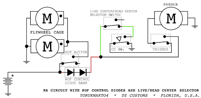
That is where diodes go. Between the battery and the ENTIRE pusher circuit.
A common ROF drop diode is the 1N5400 series - cheap, all of which are rated for the voltages involved, and rated for 5 amps continuous and able to handle FK-180SH-3240 pusher motors easily on intermittent duty like shooting. Each diode drops somthing vaguely around a volt and you can use as many in series as necessary. (Do not parallel them, they will not share current because they aren't linear, if you want to throttle a larger motor load down you need to get a bigger single diode.)
You can wire diodes in any fashion you like, including switched banks for variable-ROF operation on the fly, as in my 2013 RapidSwarm. Also note that this schematic includes a switch to change between live center and dead center control. These are just a few of the examples of ways to soup up the control wiring of the RS with options and features. I will cover more of them in the future.
On the subject of diodes, I have received SO many messages about problems with Rapidstrike builds and diodes, mostly of the form "I added diodes and now it doesn't work" or "I added diodes and now the pusher doesn't STOP". So I have prepared an image showing all the various wrong ways to attempt diode-drops:

- Erroneous diode in main battery lead - throttles the flywheels and will likely go pop quickly unless it is a BIG diode.
- Correct diode in positive rail to pusher circuit only.
- Erroneous diode in positive line to CC switch. This will slow only the automatic operation of the pusher in this live center RS, not operation due to trigger pull.
- (The worst offender) Erroneous diode in the positive wire to the pusher motor. This is a BIDIRECTIONAL current path. This diode will BLOCK the braking current and PREVENT motor braking.
- Erroneous diode between the pusher motor and ground, to the same effect as above.
- Erroneous diode in the positive line to the trigger switch will drop only trigger pull operation and allow the pusher motor to accelerate when cutting to automatic control, which will reduce ROF without stability benefit.

This is popularized by the UK community and recommended by Blastersmiths UK.
Note that without the rev switch pulled in, the pusher circuit cannot get any power, and cannot fire.
Pros:
- Noobs can't mash a dart into stationary flywheels, causing a stoppage.
- Greater safety, since the pusher circuit is disconnected behind a normally-open switch in an idle gun. Like the dead center circuit, no bolt movement or mechanical failure of the cycle control hardware can make it start up accidentally or randomly.
- Less potential for damage by obstruction, since the rev switch kills the power to the pusher circuit. Releasing it will disconnect a crashed pusher and alleviate the overcurrent and torque.
- Less flexibility for experienced operators. I might shoot unpowered flywheels that are still turning - the 180 armature and flywheel has enough inertia to fire a very decent shot in such a situation. This is one more added way I can avoid being tagged in HvZ; plus I cannot guarantee I always have the switch on when I pull the trigger if I am shooting occasionally and being "blippy" with the motors. Yes, in this strategy, the back-EMF of the rotating flywheel motors will in fact power the pusher, but this is taking residual energy out of the flywheels when you need it to impart kinetic energy to that dart you just fed.
- All the current passes through the rev switch. Especially where a submini switch is used, but even with full-size name brand high rated micros, it bugs me a little.
Coming soon: Pictorial diagrams showing real parts and wiring connections.
Battery Positions, front wiring, rear wiring
FCG Build Guide.
Cycle Control Followers. Timing, Duration and all that voodoo.
Flywheel cage wiring methods.
Connectors for internal modularity.
Circuit protection R&D.
Great write-up, I applaud the time you've taken to detail out each build spec along with the pros/cons that accompany each. Although I've stepped out of mainstream nerf for awhile, I find it reliving that community members are still doing great scientifically-backed work, and actually working with and helping other members of the NIC that may not quite understand the technically of the hobby. To that, I salute you all over here at Dart Zone.
ReplyDeleteI second that. Thanks for breaking it down for those of us who are less tech savvy.
ReplyDeleteWhere is the negative?
ReplyDeleteWhat do you mean?
DeleteI showed numerous ground connections in the diagrams (negative ground system here) to reduce clutter. All those need to be connected by wire in the real harness.
The live center circuit is messed up. The normally open and normally closed of the cycle control switch should be switched. Also the red wire (where you would put diodes for ROF control) should be connected to the normally open of the rev trigger to prevent pusher jams. I spent two hours trying to fix these problems.
ReplyDeletePlease pay some attention. I state that the cycle control switch is not shown at rest, it is shown actuated in the diagrams to reflect its state in typical installations. All of the diagrams show a limit switch that is being depressed.
DeleteAbout the red wire, again, read the post. That interlock scheme and the reasons for running or not running it is covered. In detail. You are looking at the difference between British and American wiring and both are shown.
Sorry I was mistaken.
Delete