
Box contents.

This is the stock battery tray. Extra spring terminals in the middle of the stick for extra resistance!

Battery tray removal. You will run into these triangular drive screws securing the buttplate/battery box cover to the battery tray. Same as Stampede buttplate/battery tray assemblies, the uncommon drive is used to stop people from absentmindedly unscrewing the wrong screws trying to open the battery box.
If you do not have the proper driver for these, which I do not in this location, try household scissors. The blade tip is likely to engage the screw well enough to back it out with minimum hassle. Don't use a good pair of scissors for this, of course.

Then put your cover back together with standard screws.
Zeus vs. Tacmod 3.1

Not a small gun. Quite a chunky thing this is.
Eotech test:

See how small the 552 is in comparison to the Zeus?
The rail length works, but unfortunately, these rails (which are very sloppily made Hasbro rail that LOOKS like Picatinny) suck, and my sight has an unsettling list to it when tightened up, along with thin-plasticky flex:

That's a big nope, looks like this thing is getting picatinnied in the future. Time to order some Magpul rail sections.
Here's a weird observation:

"Rating:
...Wait, what?

9.6V?????
Speculation time: Alkaline tray is an afterthought? Nerf has rechargeable plans? 9.6 is such a specific voltage. Why?

Mag release. Spring seat is an integral part. Quick observation with this, it is reversible in the receiver. If you are having trouble releasing mags from your chosen side, try flipping this over with the spring seat arm facing the other way.

Plenty of room in this battery box after de-traying. Also, plenty more room is available if the webbing is gutted out. Betcha you could fit a double stick sub-C pack or a regular "brick" shaped lipo in there with some careful grinding. You may have to rethink the cover anchor nuts though.

Top rail is a separate part integral with the rear sight base. It is clamshell but doesn't need to be. This will be taken advantage of when installing picatinny, since I see zero reason to ever open or paint this thing later on I will likely just weld it together with a plate on top for bolting the rail.

Same old crap wire, this is the same 22AWG? or so stuff used in the nerf AEGs

The masking tape is a nice touch.

Boo.
Hiss.

PTC on that little board at left

Flywheel cage removed. The breech/feed assembly is integral. It also isn't a closed cage. This side is open through the jam port on the side. Very cool.
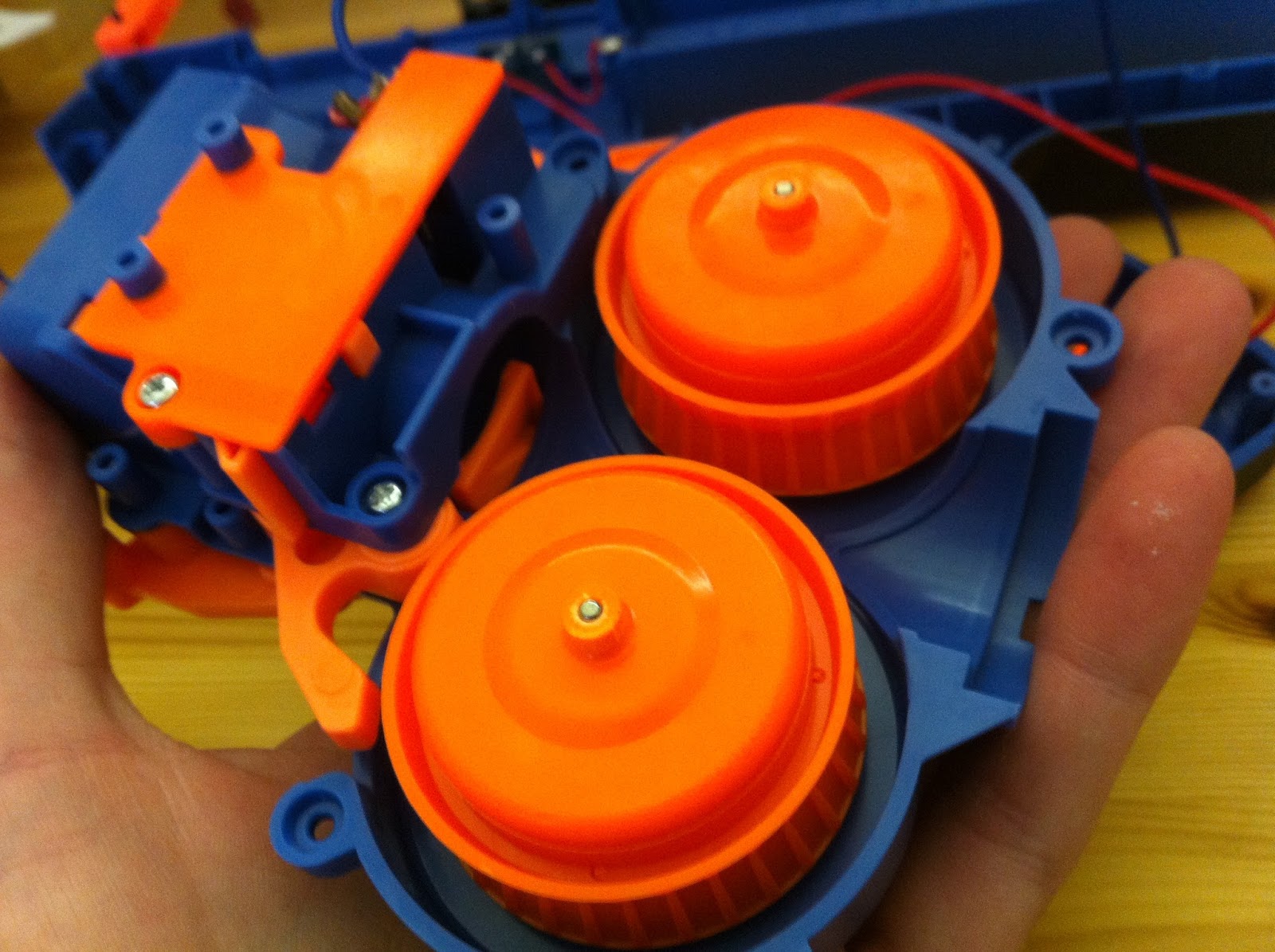
Flywheel comparison to RS fly. Do you get a sense of scale NOW? These flywheels are huge. No wonder they have 300 series motors on them! They are made of ABS. Balance issues are notable here. Noise and vibration are high.

Lock removal: Orange plate on the right (jam door) side of the breech assembly. It's a real Rube Goldberg mess in there - mag and jam door interlocks all interlocked! You can't rev or pull the trigger without a mag loaded and the jam door closed.
All of it can go. The plate, all the plastics, one spring, the switch, and the screw. All the gate linkage that is actually important is on the other side, the one with the motor endbells that faces out when installed.
None of this hardware latches the jam door! That is done by the rails it runs on and its associated mounting hardware in the receiver. Removing this stuff will not make it loose or change the feel at all.

Dart experiment.

Breech. You can see the raised detent at the right. You may have seen the uncontrolled feed full auto mod, and that this detent needs to be removed. This is the prime reason why that modification is not something to do lightly. The detent's function will be explained shortly.

This is at rest. The orange gate you can see closed is the front gate. There is a second gate at the rear, one round length away from the front gate.

With one ball in the breech.

Pulling the trigger. The rear gate pops out and blocks off the mag, preventing further rounds from feeding. At the same time, the front gate retracts.
This does not fire the ball, however. The ball remains held in the breech by the detent.
What gets the ball past the detent is the orange part seen at the bottom of the chamber, which will be called the ram. It is a lever that pivots about a horizontal axis.

Continuing to pull the trigger, the front cam pin on the trigger engages the ram and causes it to flip up and force the ball past the detent, where it is seized by the flywheels.

Zip!
Now here is the hopup system.


This needs to be targeted for additional testing (starting with temporary removal of the inner barrel to establish unhopped ballistics). Whether the hopups on Rival guns (commercial or DIY) are modified, adjusted, replaced, or worried over like airsoft ones to increase the consistency of the backspin and thus accuracy, are is all down to the ability of the ammo to support accuracy.
Polyurethane foam balls, a sketchy proposition in some ways.
Rev switch is a dual contact type, familiar to Stampede and Nitron users. In some ways the grip is Nitronnish as well. Typical trigger interlock here.

Trigger; front cam pin is for the ram lever, the top ramp is for operating the gates.

Microswitch mockup.

Cleaned up motor terminals. I never got a picture of it, but there are axial lead inductors, those 2 PCBs shown, and ceramic disc caps stock.
Motor clamps are plastic and are bolted down hard. They clamp the motor into what seems like a rubber lined mount, as in Stampede gearboxes. The motor can does not press fit into the cage. There is also no glue, unless some hotglue was spilled from the electrical component and solder joint reinforcing/supporting use of this stretchy hot melt goop all over the inside of these things.

Grip gutting for switch.


14AWG teflon, note green is negative, but I turned my motors around from stock to get positve on front. I find it best to send the flywheel leads upward, you want to keep wire well away from the trigger area.

While on the subject of motors - the zeus motor is a 360, confirmed to be a 3 pole motor. I have not pulled the flies or removed the motors yet and still no idea on winding data or kv. It isn't a standard metal endbell Mabuchi or a Mabuchi clone; it is nylon endbell, and may be a Johnson. It does have a bronze sleeve bearing in the endbell so shouldn't have any problems with that.

Minor wire clearance


And that's all folks!

Shoots like a beast on 2S.

While I was at it, I grabbed this top rail length (6") for proper Picatinny replacements.

Yes, I know - What about X? Where's the data? It's coming. Hold on.
Update 08-04
Preliminary chrono shots:
7.4V: 91.72, 100.3, 96.74, 94.02, 93.21, 100.3
11.1V: 115.5, 105.4, 110.3, 105.3, 107.7, 105.7
14.8V: 108, 106.9, 110
Feet per second. New ammo. Sample size is crap because I have only 12 rounds and I don't want wear affecting the data.
As you can see, 3S definitely gained something over 2S, but there is certainly some dynamic-friction action going on in the 110-115 fps band, 4S only added noise and ammo wear (observed as an increase in foam "sparks" coming out the muzzle). I would say 2S is right on the edge of criticality, probably right in the knuckle of the curve where it transitions from static friction to dynamic friction and starts approaching the ~110 fps asymptote. For that matter, the stock alkalames are probably near there as well, only much saggier and more gutless. The 2S pack (I am using my new 25R Sammy stick) makes it a lot more shootable and responsive than the stock reviewers are reporting.

The location of the criticality barrier of this system so close to stock suggests they engineered and optimized the hell out of it, in terms of shooting harder at least. Doesn't mean 15-20 fps and speed headroom is not a major, major upgrade.
This is all tested with the hop-up installed.
Next step is to work out power systems that will give more torque with similar speed to 3S with stock motors, since that seems to be right about what it wants. I suspect this will end up as a matter of matching the kv of the stock motors 1:1, as 3S batteries seem like the way forward.
3S is about the maximum voltage you would want to deal with (pack size and cost wise), and compared to 2S, higher voltage is always better if it is possible - with a higher turn count motor you get better copper fill, more torque, and more efficiency, and deliver the same power with less current, thus less brush wear and less losses over stray resistances and battery sag. Also, 3S is a convenient way to do things for the NIC because the battery requirement would not change between stock motor "stage 1" builds and aftermarket motor "stage 2" builds. Get a good pack and you are futureproofed.
Speaking of motors, the stock ones are not half bad. On 3S the response is there. For semi-auto and mechanical full auto at a reasonable rate (not 25rps uncontrolled feed...) they really ought to be good enough for anyone with a 3S battery and rewire, or even 2S.
> "9.6 is such a specific voltage. Why?"
ReplyDelete9.6 is 8 x 1.2. It looks like Hasbro was planning on using NiMH.
Obviously, that is what I meant/was getting at.
DeleteOr a 3S LiFePO4, often identified as 3.2V/cell.
I find it interesting you went with blue - considering your DZ customs red superstock blasters. Was a blue Zeus the only one available?
ReplyDeleteIt was what the Target employee retrieved from the stockroom. The stock Rival red is not the right red to match my gear anyway.
DeleteI figured the Zeus would have potential, but mag changes look like a pain. What are your thoughts?
ReplyDeleteI will be working on fixes soon.
DeleteJust got finished rewiring mine. Does yours howl pretty loud on 3S due to the empty space left by removing the battery tray? I am finding tons of acoustic amplification due the large hollow body.
ReplyDeleteYes, it is loud as hell, It isn't the battery tray that I suspect is the cause (the tray doesn't fit tightly against anything to damp vibration), it is mainly the flat empty areas up front. Grabbing the forend tightly can hush the noise a bit. I am planning to do something in that area to rigidize, add mass, or add absorption. Maybe azrael's Dynamat usage will come in handy here.
DeleteThe root cause is the imbalance of the flywheels. I want to look into balancing or having them balanced by a machine shop with the appropriate tools.
Dynamic balancing is probably cheaper than Dynamat overall, with the added vibration and wear drop factored in too.
DeleteThanks for a solid write up too.
I wonder if putting in foam in the dead space areas would help reduce vibration and sound the same way that people would stuff foam tubing into the ERTL PAS to reduce noise.
DeleteThe Modulus is where it belongs :P
ReplyDeleteSo... what motor to upgrade...
ReplyDeleteFYI, I measured the battery tray to be 25mm width and height, but if you remove the upper portion of the tray, then you can fit a battery 25mm width x 33mm height. Also, what discharge rate are you using?
ReplyDeleteThe battery box is a lot bigger than 25mm. A C cell is a 26500 (26mm) and the tray around that adds a few more mm on the sides.
DeleteWhat do you mean by upper portion? There is plenty of webbing to gut out and that would yield mega room inside though.
I am using 18650 power tool cell packs. These vary from 1300 to 2500 mAh but are all 12-13mohm IR cells. So comparable to a ~1500 mah 20C+ (honestly rated) lipo pack's actual performance.
I was referring to the size of the stock tray if someone wanted to keep it unmodded and use it the way it is, but yes you are right, there is plenty of room for multiple battery sizes. The upper portion I was referring to was the battery tray itself, it comes in two pieces and removing the rounded section can help free more space.
DeleteThis comment has been removed by the author.
ReplyDeleteWhat kind of switch is that and where can I find it? I wanna run a 2200 mAh 30C 3S pack, so 60 Amps or so. Will that switch allow it to dump that much amperage? And will a smaller switch burn out on me?
ReplyDeleteThat is a standard microswitch. You can get them from electronic component suppliers (Digikey, etc.) or on ebay.
DeleteLook for the highest current rating you can get, and whatever actuator (lever) style you need. I recommend the Omron V-214-1C6 as a direct replacement for this switch that I used. These are the best you can get, rated for 21A which is a continuous current (they are specified to handle much larger inrush currents for motors up to and including that 60 amps).
Ratings aren't so much a matter of performance as switch life. Yes, a smaller switch could burn up. This green one is a cheap 10A generic. It's doing OK with the 390 motors so far but I am aware that isn't going to last that long. It was temporary and I am expecting to replace it with a better one or use a relay.
Awesome! Thanks, man! There's a Murphy's Electronic Surplus near me, I'll see if I can find one!
ReplyDeleteSo what size are these motors?
ReplyDelete360
DeleteMy son burnt out the motor when he jammed a ball and held down the trigger for about 8 sec.
DeleteIf you have any Stampede, Swarmfire or Vulcan stock motors sitting around, those should do OK as a swap. You can put any common 380 or 390 in those AEGs without a concern, but putting anything torquier than the 60t 360 motor on the stock zeus flywheels may cause problems.
DeleteGreat write up. Mine worked for about two weeks solid then the motors burnt out. I suspect the 3s was a bit too much and maybe the C rating was too high. I think I will try a different battery next. Or I will find some new motors. Im on the fence. It may be cheaper just to buy a new gun and start over.
ReplyDeleteI strongly doubt that you actually had a motor burnout. I ran these on 4S after lightning linking for a while and many others are using them on 3S with high-cap hopper and air feed systems and shooting a ton nonstop and haven't blown any of them.
DeleteWere you using a stock switch? it would be expected to crater about that fast. Have you tested every component in your wiring harness yet?
How are you connecting the 25r batteries together?
ReplyDeleteHow are you connecting the 2 25r batteries together? I want to get them on amazon but don't do much electrical and want to make sure I pick up the right stuff. All other mods are ready, just need a new battery.
ReplyDeleteThat is a pack and the cells are connected by spot welded nickel tabs. I built equipment to do this.
DeleteI would recommend you use a commercially available NiMH or LiPo battery. If you want one of my batteries, then I do sell them.
Hey guys I'm thinking of running Imr's in a c shell converter. The battery's are 14500.
ReplyDeleteI was wondering how many I need and if this is a good idea. I am new too any serious internal mods except removing mechanical locks. Any help will be insanely appreciated.
Thx
14500 "IMR" cells and the contact holders that you use to connect loose cells to the harness are both *not* suitable for almost any nerf application. The cells have way too low a current rating and way too high an internal resistance, thus will give subpar performance and be overstressed and fail sooner. The cell holders can also fail due to heating of the contact and are a major issue with parasitic resistance.
DeleteThis is especially the case with the two 360 stock motors and big flywheels in a Zeus.
Use a pack.
Thanks
DeleteHow well would the motors hold up to 3s LiPO packs (3.7v nominal)? I have a ton of packs from rc planes and quadcopters, would rather use something I already have than buy LiFE packs.
ReplyDelete3s LiPO is less voltage than 4s LiFE, but might be too much for long life on the stock motors?
These motors are normally run on 3S lipo/3.7V (11.1V).
DeleteIn general, LiFePO4 is not very popular. I don't know of anyone using it in this app.